Toyota Yaris: Lane Tracing Assist System / Steering Pad Switch Circuit
DESCRIPTION
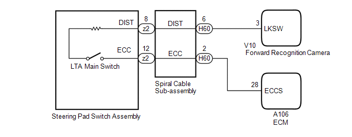
The forward recognition camera receives LTA main switch signals from the steering pad switch assembly.
WIRING DIAGRAM
CAUTION / NOTICE / HINT
NOTICE:
- When replacing the forward recognition camera, always replace it with a new one. If a forward recognition camera which was installed to another vehicle is used, the information stored in the forward recognition camera will not match the information from the vehicle and a DTC may be stored.
-
When the forward recognition camera is replaced with a new one or the windshield glass is replaced or removed/installed, make sure to read Before Starting Adjustment, then perform optical axis alignment for the forward recognition camera and clear the vehicle control history for each system.
HINT:
Forward recognition camera axis alignment can be performed by using either One Time Recognition, Sequential Recognition or Driving Adjustment.
One time recognition: Click here

Sequential recognition: Click here

Driving Adjustment: Click here

-
During the steering pad switch assembly check, check the precautions for the airbag system since the horn button assembly is removed during servicing. (installation/removal of parts, checks, replacement, etc.)
Click here

PROCEDURE
| 1. | READ VALUE USING GTS (LDA CONTROL) |
(a) Read the Data List according to the display on the GTS.
Chassis > Lane Control > Data List| Tester Display | Measurement Item | Range | Normal Condition | Diagnostic Note |
|---|---|---|---|---|
| LDA Control | Whether lane tracing assist system control is permitted or not | Prohibit or Permit | Prohibit: Lane tracing assist system control not possible Permit: Lane tracing assist system control possible | - |
| Tester Display |
|---|
| LDA Control |
| Result | Proceed to |
|---|---|
| Data List value changes when LTA Main Switch is operated | A |
| Data List value does not change when LTA Main Switch is operated | B |
| A |
 | PROCEED TO NEXT SUSPECTED AREA SHOWN IN PROBLEM SYMPTOMS TABLE |
|

| 2. | INSPECT STEERING PAD SWITCH ASSEMBLY |
Click here

| NG |
 | REPLACE STEERING PAD SWITCH ASSEMBLY |
|

| 3. | INSPECT SPIRAL CABLE SUB-ASSEMBLY |
Click here

| NG |
 | REPLACE SPIRAL CABLE SUB-ASSEMBLY |
|

| 4. | CHECK HARNESS AND CONNECTOR (SPIRAL CABLE SUB-ASSEMBLY - FORWARD RECOGNITION CAMERA) |
(a) Disconnect the H60 spiral cable sub-assembly connector.
(b) Disconnect the V10 forward recognition camera connector.
(c) Measure the resistance according to the value(s) in the table below.
Standard Resistance:
| Tester Connection | Condition | Specified Condition |
|---|---|---|
| H60-6 (DIST) - V10-3 (LKSW) | Always | Below 1 Ω |
| H60-6 (DIST) or V10-3 (LKSW) - Body ground | Always | 10 kΩ or higher |
| NG |
 | REPAIR OR REPLACE HARNESS OR CONNECTOR |
|

| 5. | CHECK HARNESS AND CONNECTOR (SPIRAL CABLE SUB-ASSEMBLY - ECM) |
(a) Disconnect the H60 spiral cable sub-assembly connector.
(b) Disconnect the A106 ECM connector.
(c) Measure the resistance according to the value(s) in the table below.
Standard Resistance:
| Tester Connection | Condition | Specified Condition |
|---|---|---|
| H60-2 (ECC) - A106-28 (ECCS) | Always | Below 1 Ω |
| H60-2 (ECC) or A106-28 (ECCS) - Body ground | Always | 10 kΩ or higher |
| OK |
 | REPLACE FORWARD RECOGNITION CAMERA |
| NG |
 | REPAIR OR REPLACE HARNESS OR CONNECTOR |
 Internal Control Module Software Incompatibility Not Programmed (U030051,U030057)
DESCRIPTION The forward recognition camera receives vehicle information from the ECM via the CAN communication line. If the forward recognition camera cannot confirm the vehicle information sent from the ECM, the forward recognition camera stores DTC U030051...
 Indicator Circuit
DESCRIPTION The forward recognition camera sends indicator illumination request signals to the combination meter assembly via CAN communication. CAUTION / NOTICE / HINT NOTICE: When replacing the combination meter assembly, always replace it with a new one...
Categories
- Manuals Home
- Toyota Yaris Owners Manual
- Toyota Yaris Service Manual
- Brake System Control Module "A" System Voltage System Voltage Low (C137BA2)
- Engine Start Function When Key Battery is Dead
- How to connect USB port/Auxiliary jack
- New on site
- Most important about car
Liftgate/Trunk Lid
WARNING
Never allow a person to ride in the luggage compartment/trunk
Allowing a person to ride in the luggage compartment/trunk is dangerous. The person in the luggage compartment/trunk could be seriously injured or killed during sudden braking or a collision.
Do not drive with the liftgate/trunk lid open