
Toyota Yaris: Lane Tracing Assist System / Indicator Circuit
DESCRIPTION
The forward recognition camera sends indicator illumination request signals to the combination meter assembly via CAN communication.
CAUTION / NOTICE / HINT
NOTICE:
When replacing the combination meter assembly, always replace it with a new one. If a combination meter assembly which was installed to another vehicle is used, the information stored in the combination meter assembly will not match the information from the vehicle, and may cause a DTC to be output.
PROCEDURE
| 1. | READ VALUE USING GTS (CAN BUS CHECK) |
(a) Using the GTS, perform CAN bus diagnostics and check that there are no malfunctions in ECUs connected to the CAN communication system.
Click here
CAN Bus Check
| Result | Proceed to |
| CAN communication system is normal (DTC (CAN Communication Malfunction, ECU Communication Malfunction/Communication Lost) is not output) | A |
| CAN communication system is malfunctioning (DTC (CAN Communication Malfunction, ECU Communication Malfunction/Communication Lost) is output) | B |
| B |
| GO TO CAN COMMUNICATION SYSTEM |
|
A |
| |
| 2. | CHECK FOR DTCs (HEALTH CHECK) |
(a) Using the GTS, perform a health check.
| Result | Proceed to |
| DTCs are not output. | A |
| DTCs are output. | B |
| B |
| GO TO DTC CHART |
|
A |
| |
| 3. | PERFORM ACTIVE TEST USING GTS (MULTI DISPLAY ALL (WHITE)) |
(a) Using the GTS, perform the Active Test.
Body Electrical > Combination Meter > Active Test
| Tester Display | Measurement Item | Control Range | Diagnostic Note |
| Multi Display All (White) | Multi-information display (White display) | ON | Confirm that the vehicle is stopped with the ignition switch ON. |
Body Electrical > Combination Meter > Active Test
| Tester Display |
| Multi Display All (White) |
| Result | Proceed to |
| The multi-information display in the combination meter assembly turns on according to the operation of the Active Test. | A |
| The multi-information display in the combination meter assembly does not turn on according to the operation of the Active Test. | B |
| A |
| PROCEED TO NEXT SUSPECTED AREA SHOWN IN PROBLEM SYMPTOMS TABLE |
| B |
| REPLACE COMBINATION METER ASSEMBLY |
DESCRIPTION The forward recognition camera receives LTA main switch signals from the steering pad switch assembly. WIRING DIAGRAM
CAUTION / NOTICE / HINT NOTICE:
When replacing the forward recognition camera, always replace it with a new one...
Other information:
DESCRIPTION DTC No. Detection Item DTC Detection Condition Trouble Area Warning Indicate Return-to-normal Condition Note C05D604 Power Steering Control Module Processor System Internal Failure ECU internal malfunction (CPU malfunction) Power steering ECU assembly EPS warning light: Comes on Ignition switch ON again - C05D646 Power Steering Control Module Processor Calibration / Parameter Memory Failure ECU internal malfunction (EEPROM error) Power steering ECU assembly EPS warning light: Comes on Ignition switch ON again - C05D649 Power Steering Control Module Processor Internal Electronic Failure ECU internal malfunction (Peripheral circuit malfunction) Power steering ECU assembly EPS warning light: Comes on Ignition switch ON again - C10001C Control Module Internal Temperature Sensor "A" Circuit Voltage Out of Range ECU temperature sensor "A" range malfunction Power steering ECU assembly EPS warning light: Comes on The ECU judges the system has returned to normal - C152A18 Power Steering Motor "A" Circuit Current Below Threshold Motor "A" low current malfunction Power steering ECU assembly EPS warning light: Comes on Ignition switch ON again - C152A19 Power Steering Motor "A" Circuit Current Above Threshold Motor "A" overcurrent Power steering ECU assembly EPS warning light: Comes on Ignition switch ON again - C152B18 Power Steering Motor "B" Circuit Current Below Threshold Motor "B" low current malfunction Power steering ECU assembly EPS warning light: Comes on Ignition switch ON again - C152B19 Power Steering Motor "B" Circuit Current Above Threshold Motor "B" overcurrent Power steering ECU assembly EPS warning light: Comes on Ignition switch ON again - C153A00 Malfunction of Power Steering Motor "A" Inverter Pre-Driver Inverter "A" pre-driver circuit malfunction Power steering ECU assembly EPS warning light: Comes on Ignition switch ON again - C153A19 Power Steering Motor "A" Inverter Circuit Current Above Threshold Inverter "A" short circuit malfunction Power steering ECU assembly EPS warning light: Comes on Ignition switch ON again - C153B00 Malfunction of Power Steering Motor "B" Inverter Pre-Driver Inverter "B" pre-driver circuit malfunction Power steering ECU assembly EPS warning light: Comes on Ignition switch ON again - C153B19 Power Steering Motor "B" Inverter Circuit Current Above Threshold Inverter "B" short circuit malfunction Power steering ECU assembly EPS warning light: Comes on Ignition switch ON again - C154A7E Power Supply & Contrary Connection Protection Relay "A" Actuator Stuck On Contrary connection protection relay "A" short circuit malfunction (initial check) Power steering ECU assembly EPS warning light: Comes on Ignition switch ON again - C154A7F Power Supply & Contrary Connection Protection Relay "A" Actuator Stuck Off Contrary connection protection relay "A" open circuit malfunction (initial check) Power steering ECU assembly EPS warning light: Comes on Ignition switch ON again - C154B7E Power Supply & Contrary Connection Protection Relay "B" Actuator Stuck On Contrary connection protection relay "B" short circuit malfunction (initial check) Power steering ECU assembly EPS warning light: Comes on Ignition switch ON again - C154B7F Power Supply & Contrary Connection Protection Relay "B" Actuator Stuck Off Contrary connection protection relay "B" open circuit malfunction (initial check) Power steering ECU assembly EPS warning light: Comes on Ignition switch ON again - C157A11 Power Steering Motor "A" Current Sensor Circuit Short to Ground Motor "A" current sensor low voltage malfunction Power steering ECU assembly EPS warning light: Comes on Ignition switch ON again - C157A62 Power Steering Motor "A" Current Sensor Signal Compare Failure Motor "A" current sensor correlation malfunction Power steering ECU assembly EPS warning light: Comes on Ignition switch ON again - C157B11 Power Steering Motor "B" Current Sensor Circuit Short to Ground Motor "B" current sensor low voltage malfunction Power steering ECU assembly EPS warning light: Comes on Ignition switch ON again - C157B62 Power Steering Motor "B" Current Sensor Signal Compare Failure Motor "B" current sensor correlation malfunction Power steering ECU assembly EPS warning light: Comes on Ignition switch ON again - C15D11C Power Steering Motor Position Sensor "A" Circuit Voltage Out of Range Rotation angle sensor "A" range malfunction Power steering ECU assembly EPS warning light: Comes on Ignition switch ON again - C15D162 Power Steering Motor Position Sensor "A" Signal Compare Failure Rotation angle sensor "A" correlation malfunction Power steering ECU assembly EPS warning light: Comes on Ignition switch ON again - C15D21C Power Steering Motor Position Sensor "B" Circuit Voltage Out of Range Rotation angle sensor "B" range malfunction Power steering ECU assembly EPS warning light: Comes on Ignition switch ON again - C15D262 Power Steering Motor Position Sensor "B" Signal Compare Failure Rotation angle sensor "B" correlation malfunction Power steering ECU assembly EPS warning light: Comes on Ignition switch ON again - C15D31C Power Steering Motor Position Sensor "C" Circuit Voltage Out of Range Rotation angle sensor "C" range malfunction Power steering ECU assembly EPS warning light: Comes on Ignition switch ON again - C15D362 Power Steering Motor Position Sensor "C" Signal Compare Failure Rotation angle sensor "C" correlation malfunction Power steering ECU assembly EPS warning light: Comes on Ignition switch ON again - CAUTION / NOTICE / HINT NOTICE: When the power steering ECU assembly has been replaced, perform Power Steering ECU Initial Setting (assist map writing)...
TERMINALS OF ECU CHECK CERTIFICATION ECU (SMART KEY ECU ASSEMBLY)
(a) Disconnect the H46 certification ECU (smart key ECU assembly) connector. (b) Measure the voltage and resistance according to the value(s) in the table below. Tester Connection Terminal Description Condition Specified Condition Related Data List Item H46-29 (E) - Body ground Ground Always Below 1 Ω - H46-6 (+B) - H46-29 (E) Power supply Always 11 to 14 V - H45-22 (CUTB) - H46-29 (E) Dark current cut pin* Ignition switch off 11 to 14 V -
*: In order to prevent the vehicle auxiliary battery from being depleted when the vehicle is shipped long distances, a fuse that cuts unnecessary electrical load while the vehicle is being shipped is installed in the circuit...
Categories
Before refueling, close all the doors, windows, and the liftgate/trunk
lid, and switch the ignition OFF.
To open the fuel-filler lid, pull
the remote fuel-filler lid release.
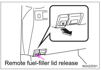
To remove the fuel-filler cap, turn it counterclockwise.
Attach the removed cap to the
inner side of the fuel-filler lid.
read more