Toyota Yaris: Smart Key System (for Start Function) / Steering Lock Confirmation Signal Circuit Voltage Out of Range (B279F1C)
DESCRIPTION
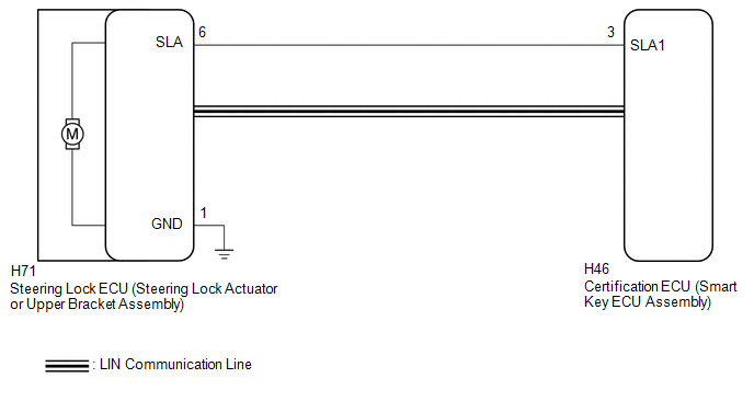
This DTC is stored when the SLA input (the steering lock motor activation permission signal) sent directly from the certification ECU (smart key ECU assembly) to the steering lock ECU (steering lock actuator or upper bracket assembly) is determined to be abnormal.
HINT:
The steering lock ECU (steering lock actuator or upper bracket assembly) is not connected to the CAN communication system. However, the steering lock ECU (steering lock actuator or upper bracket assembly) is connected to the certification ECU (smart key ECU assembly) via LIN communication and communicates with other components via CAN communication through the certification ECU (smart key ECU assembly).
| DTC No. | Detection Item | DTC Detection Condition | Trouble Area | Note |
|---|---|---|---|---|
| B279F1C | Steering Lock Confirmation Signal Circuit Voltage Out of Range | Either of the following conditions is met (1-trip detection logic*):
|
| DTC Output Confirmation Operation:
|
- *: Only detected while a malfunction is present and the ignition switch is ON.
| Vehicle Condition when Malfunction Detected | Fail-safe Function when Malfunction Detected |
|---|---|
| The steering cannot be locked or unlocked. For this reason, the engine cannot be started. | Prohibits the engine from being started (the engine does not start). |
| DTC No. | Data List and Active Test |
|---|---|
| B279F1C | - |
WIRING DIAGRAM
CAUTION / NOTICE / HINT
NOTICE:
- When using the GTS with the ignition switch off, connect the GTS to the DLC3 and turn a courtesy light switch on and off at intervals of 1.5 seconds or less until communication between the GTS and the vehicle begins. Then select the vehicle type under manual mode and enter the following menus: Body Electrical / Smart Key. While using the GTS, periodically turn a courtesy light switch on and off at intervals of 1.5 seconds or less to maintain communication between the GTS and the vehicle.
-
The smart key system (for Start Function) uses the LIN communication system and CAN communication system. Inspect the communication function by following How to Proceed with Troubleshooting. Troubleshoot the smart key system (for Start Function) after confirming that the communication systems are functioning properly.
Click here

-
Before replacing the steering lock ECU (steering lock actuator or upper bracket assembly) or certification ECU (smart key ECU assembly), refer to Registration.
Click here

- After performing repairs, confirm that no DTCs are output by performing "DTC Output Confirmation Operation".
HINT:
When disconnecting and reconnecting the auxiliary battery, there is an automatic learning function that completes learning when the respective system is used.
Click here

PROCEDURE
| 1. | CHECK FOR DTC |
(a) Using the GTS, check if LIN communication DTC B278588 is output.
Body Electrical > Smart Key > Trouble Codes| Result | Proceed to |
|---|---|
| DTC B278588 is not output | A |
| DTC B278588 is output | B |
| B |
 | GO TO LIN COMMUNICATION SYSTEM (DTC B278588) |
|

| 2. | CHECK STEERING LOCK ECU (STEERING LOCK ACTUATOR OR UPPER BRACKET ASSEMBLY) |
(a) Disconnect the H71 steering lock ECU (steering lock actuator or upper bracket assembly) connector.
(b) Measure the resistance according to the value(s) in the table below.
Standard Resistance:
| Tester Connection | Condition | Specified Condition |
|---|---|---|
| H71-1 (GND) - Body ground | Always | Below 1 Ω |
(c) Reconnect the H71 steering lock ECU (steering lock actuator or upper bracket assembly) connector.
(d) Measure the voltage according to the value(s) in the table below.
Standard Voltage:
| Tester Connection | Condition | Specified Condition |
|---|---|---|
| H71-6 (SLA) - H71-1 (GND) | Ignition switch off | Below 1 V |
| H71-6 (SLA) - H71-1 (GND) | Ignition switch ON | 11 to 14 V |
| NG |
 | GO TO STEP 5 |
|

| 3. | CLEAR DTC AND DATA LIST MALFUNCTION RECORD |
(a) Clear the DTCs.
Body Electrical > Smart Key > Clear DTCs(b) Disconnect the cable from the negative (-) auxiliary battery terminal, wait for 30 seconds or more, and then reconnect the cable to the negative (-) auxiliary battery terminal to clear the record of malfunctions stored in the Data List.
HINT:
When disconnecting and reconnecting the auxiliary battery, there is an automatic learning function that completes learning when the respective system is used.
Click here

|

| 4. | CHECK FOR DTC |
(a) Perform the DTC output confirmation operation.
(b) Check if DTC B279F1C is output.
Body Electrical > Smart Key > Trouble Codes| Result | Proceed to |
|---|---|
| DTC B279F1C is output | A |
| DTC B279F1C is not output | B |
| A |
 | REPLACE STEERING LOCK ECU (STEERING LOCK ACTUATOR OR UPPER BRACKET ASSEMBLY) |
| B |
 | SYSTEM RETURNED TO NORMAL (DTC STORED DUE TO BAD CONNECTION, BUT SYSTEM RETURNED TO NORMAL BY RECONNECTING CONNECTOR) |
| 5. | CHECK HARNESS AND CONNECTOR (STEERING LOCK ECU STEERING LOCK ACTUATOR OR UPPER BRACKET ASSEMBLY) - CERTIFICATION ECU (SMART KEY ECU ASSEMBLY)) |
(a) Disconnect the H71 steering lock ECU (steering lock actuator or upper bracket assembly) connector.
(b) Disconnect the H46 certification ECU (smart key ECU assembly) connector.
(c) Measure the resistance according to the value(s) in the table below.
Standard Resistance:
| Tester Connection | Condition | Specified Condition |
|---|---|---|
| H71-6 (SLA) - H46-3 (SLA1) | Always | Below 1 Ω |
| H71-6 (SLA) or H46-3 (SLA1) - Other terminals and body ground | Always | 10 kΩ or higher |
| OK |
 | REPLACE CERTIFICATION ECU (SMART KEY ECU ASSEMBLY) |
| NG |
 | REPAIR OR REPLACE HARNESS OR CONNECTOR |
 Engine Immobiliser System Incorrect Assembly (B279C95)
DESCRIPTION If an ECM that is incompatible with the immobiliser function is installed, the ECM will store this DTC. DTC No. Detection Item DTC Detection Condition Trouble Area Note B279C95 Engine Immobiliser System Incorrect Assembly An ECM that is incompatible with the immobiliser function is installed...
 Front Floor Electrical Key Oscillator Circuit Open (B27A513)
DESCRIPTION The certification ECU (smart key ECU assembly) generates a request signal and transmits the signal to the No. 1 indoor electrical key antenna assembly (front floor)...
Other information:
Toyota Yaris XP210 (2020-2025) Owner's Manual: Owner Maintenance Precautions
The owner or a qualified service technician should make these vehicle inspections at the indicated intervals to ensure safe and dependable operation. Bring any problem to the attention of your Toyota dealer or qualified service technician as soon as possible...
Toyota Yaris XP210 (2020-2025) Reapir and Service Manual: Removal
REMOVAL PROCEDURE 1. RECOVER REFRIGERANT FROM REFRIGERATION SYSTEM Click here 2. REMOVE AIR CONDITIONER PRESSURE SENSOR (a) Disconnect the connector. (b) Using a 27 mm deep socket wrench, remove the air conditioner pressure sensor as shown in the illustration...
Categories
- Manuals Home
- Toyota Yaris Owners Manual
- Toyota Yaris Service Manual
- Opening and Closing the Liftgate/Trunk Lid
- Diagnostic Trouble Code Chart
- G16e-gts (engine Mechanical)
- New on site
- Most important about car
Keys

To use the auxiliary key, press the knob and pull out the auxiliary key from the smart key.
