
Toyota Yaris: Wiper Blades / Replacing Windshield Wiper Blades
Toyota Yaris XP210 (2020-2026) Owner's Manual / Maintenance and Care / Owner Maintenance / Wiper Blades / Replacing Windshield Wiper Blades
When the wipers no longer clean well, the blades are probably worn or cracked.
Replace the wiper blades using the following procedure.
- Raise the wiper arm and turn
the blade assembly to expose
the plastic locking clip.
Compress the clip and slide the assembly downward; then lift it off the arm.
BlackDiamond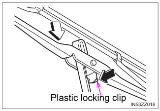
- Hold the end of the rubber and
pull until the tabs are free of the
metal support.
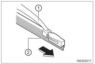
- Metal support
- Tab
- Remove the metal stiffeners
from each blade rubber and
install them in the new blade.
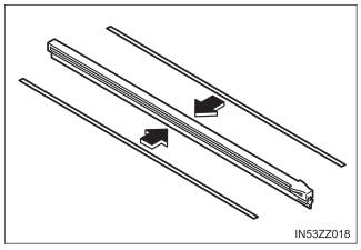
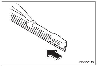
- Carefully insert the new blade
rubber. Then install the blade
assembly in the reverse order
of removal.
Install the blade so that the tabs are toward the bottom of the wiper arm.
 Wiper Blades
Contamination of either the windshield or the blades with foreign matter
can reduce wiper effectiveness. Common sources
are insects, tree sap, and hot wax treatments used by some
commercial car washes...
 Replacing Rear Window Wiper Blade (5-Door)
When the wiper no longer cleans well, the blade is probably worn or
cracked.
Replace it.
Remove the cover.
Remove the stopper and raise
the wiper arm...
Other information:
Toyota Yaris XP210 (2020-2026) Reapir and Service Manual: Terminals Of Ecu
TERMINALS OF ECU TERMINALS OF ECU *a Component without harness connected (Skid Control ECU [Brake Actuator Assembly]) - - Terminal No. (Symbol) Terminal Description 1 (GND2) Pump motor ground 2 - (Not used) 3 - (Not used) 4 - (Not used) 5 (STP2) Stop light switch assembly input 6 - (Not used) 7 - (Not used) 8 - (Not used) 9 - (Not used) 10 (CANL) CAN communication line L 11 - (Not used) 12 (IGR) ECU power supply input 13 (BM) Motor relay power supply 14 (SP1) Speed signal output for speedometer 15 (RR-) Rear wheel speed RH (-) signal input 16 (RR+) Rear wheel speed RH (+) power supply output 17 (FL-) Front wheel speed LH (-) signal input 18 (FL+) Front wheel speed LH (+) power supply output 19 - (Not used) 20 - (Not used) 21 - (Not used) 22 (CANH) CAN communication line H 23 - (Not used) 24 - (Not used) 25 (GND1) Skid control ECU (brake actuator assembly) ground 26 (STPO) Stop light switch assembly output 27 - (Not used) 28 (RL-) Rear wheel speed LH (-) signal input 29 (RL+) Rear wheel speed LH (+) power supply output 30 (FR-) Front wheel speed RH (-) signal input 31 (FR+) Front wheel speed RH (+) power supply output 32 - (Not used) 33 (CSW) VSC OFF switch (combination switch assembly) input 34 - (Not used) 35 (STP) Stop light switch assembly input 36 (CA2H) CAN communication line H 37 (CA2L) CAN communication line L 38 (+BS) Solenoid relay power supply TERMINAL INSPECTION (a) Disconnect the A108 connector and measure the voltage or resistance on the wire harness side...
Toyota Yaris XP210 (2020-2026) Reapir and Service Manual: Removal
REMOVAL CAUTION / NOTICE / HINT The necessary procedures (adjustment, calibration, initialization or registration) that must be performed after parts are removed and installed, or replaced during fuel pump removal/installation are shown below. Necessary Procedures After Parts Removed/Installed/Replaced Replaced Part or Performed Procedure Necessary Procedure Effect/Inoperative Function when Necessary Procedure not Performed Link Replacement of fuel pump Inspection after repair Poor idle, etc...
Categories
- Manuals Home
- Toyota Yaris Owners Manual
- Toyota Yaris Service Manual
- Power Integration No.1 System Missing Message (B235287,B235587,B235787-B235987)
- How to use USB mode
- Removal
- New on site
- Most important about car
Supplemental Restraint System (SRS) Precautions
The front and side supplemental restraint systems (SRS) include different types of air bags. Please verify the different types of air bags which are equipped on your vehicle by locating the “SRS AIRBAG” location indicators. These indicators are visible in the area where the air bags are installed.
The air bags are installed in the following locations:
The steering wheel hub (driver air bag) The front passenger dashboard (front passenger air bag) The outboard sides of the front seatbacks (side air bags) The front and rear window pillars, and the roof edge along both sides (curtain air bags)
Copyright © 2026 www.toyaris4.com