Toyota Yaris: Combination Meter / Removal
REMOVAL
CAUTION / NOTICE / HINT
HINT:
When the cable is disconnected/reconnected to the auxiliary battery terminal, systems temporarily stop operating. However, each system has a function that completes learning the first time the system is used.
-
Learning completes when vehicle is driven
Effect/Inoperative Function When Necessary Procedures are not Performed
Necessary Procedures
Link
Lane tracing assist system
Drive the vehicle straight ahead at 35 km/h (22 mph) or more for 5 second or more.

Pre-collision system
Stop and start system
Drive the vehicle until stop and start control is permitted (approximately 5 to 60 minutes)

-
Learning completes when vehicle is operated normally
Effect/Inoperative Function When Necessary Procedures are not Performed
Necessary Procedures
Link
Power door lock control system
- Back door opener
Perform door unlock operation with door control switch or electrical key transmitter sub-assembly switch.

Air conditioning system
After the ignition switch is turned to ON, the servo motor standard position is recognized.
-
PROCEDURE
1. PRECAUTION
NOTICE:
After turning the ignition switch off, there may be a waiting time before disconnecting the negative (-) auxiliary battery terminal.
Click here

2. DISCONNECT CABLE FROM NEGATIVE AUXILIARY BATTERY TERMINAL
Click here

3. REMOVE CENTER LOWER INSTRUMENT COVER
Click here

4. REMOVE LOWER INSTRUMENT PANEL FINISH PANEL
Click here

5. REMOVE SWITCH HOLE BASE SUB-ASSEMBLY
Click here

6. REMOVE SHIFT LEVER KNOB SUB-ASSEMBLY
Click here

7. REMOVE CONSOLE BOX ASSEMBLY
Click here

8. REMOVE FRONT DOOR SCUFF PLATE LH
Click here

9. REMOVE COWL SIDE TRIM BOARD LH
Click here

10. DISCONNECT NO. 1 ROOF HEADLINING MOULDING LH
Click here

11. DISCONNECT FRONT DOOR OPENING TRIM WEATHERSTRIP LH
Click here

12. REMOVE NO. 1 INSTRUMENT SIDE PANEL
Click here

13. REMOVE NO. 1 INSTRUMENT PANEL UNDER COVER SUB-ASSEMBLY
Click here

14. DISCONNECT HOOD LOCK CONTROL LEVER SUB-ASSEMBLY
Click here

15. REMOVE LOWER INSTRUMENT PANEL FINISH PANEL ASSEMBLY
Click here

16. REMOVE INSTRUMENT CLUSTER FINISH PANEL ASSEMBLY
Click here

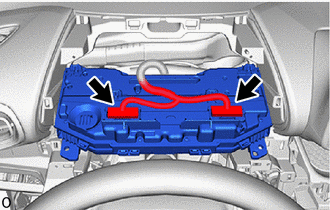
17. REMOVE COMBINATION METER ASSEMBLY
| (a) Remove the 2 screws. |
|
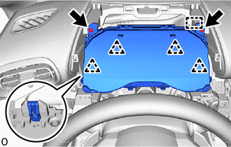
(b) Disengage the clips and guide.
| (c) Disconnect the 2 connectors to remove the combination meter assembly. |
|
 Components
COMPONENTS ILLUSTRATION
*1 LOWER INSTRUMENT PANEL FINISH PANEL *2 CENTER LOWER INSTRUMENT COVER *3 CONSOLE BOX ASSEMBLY *4 SHIFT LEVER KNOB SUB-ASSEMBLY *5 NO...
 Disassembly
DISASSEMBLY CAUTION / NOTICE / HINT NOTICE:
When removing and installing the combination meter glass, make sure not to touch the display panel.
Do not allow any dirt (fingerprints, grease, etc...
Other information:
Toyota Yaris XP210 (2020-2026) Reapir and Service Manual: Parts Location
P..
Toyota Yaris XP210 (2020-2026) Reapir and Service Manual: Diagnostic Trouble Code Chart
DIAGNOSTIC TROUBLE CODE CHART Power Steering System DTC No. Detection Item DTC Detection Condition Warning Indicate Return-to-normal Condition Note Link C05D604 Power Steering Control Module Processor System Internal Failure ECU internal malfunction (CPU malfunction) EPS warning light: Comes on Ignition switch ON again - C05D646 Power Steering Control Module Processor Calibration / Parameter Memory Failure ECU internal malfunction (EEPROM error) EPS warning light: Comes on Ignition switch ON again - C05D649 Power Steering Control Module Processor Internal Electronic Failure ECU internal malfunction (Peripheral circuit malfunction) EPS warning light: Comes on Ignition switch ON again - C10001C Control Module Internal Temperature Sensor "A" Circuit Voltage Out of Range ECU temperature sensor "A" range malfunction EPS warning light: Comes on The ECU judges the system has returned to normal - C123A17 Supply Voltage Circuit Circuit Voltage Above Threshold IG voltage is 18...
Categories
- Manuals Home
- Toyota Yaris Owners Manual
- Toyota Yaris Service Manual
- Battery Monitor Module General Electrical Failure (P058A01)
- Power Integration No.1 System Missing Message (B235287,B235587,B235787-B235987)
- Auto Lock/Unlock Function
- New on site
- Most important about car
Liftgate/Trunk Lid
WARNING
Never allow a person to ride in the luggage compartment/trunk
Allowing a person to ride in the luggage compartment/trunk is dangerous. The person in the luggage compartment/trunk could be seriously injured or killed during sudden braking or a collision.
Do not drive with the liftgate/trunk lid open