
Toyota Yaris: Headup Display System / Parts Location
PARTS LOCATION
ILLUSTRATION
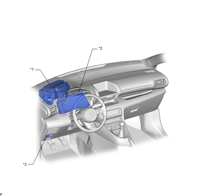
| *1 | METER MIRROR SUB-ASSEMBLY | *2 | COMBINATION METER ASSEMBLY |
| *3 | DLC3 | - | - |

 System Diagram
S..
Other information:
Toyota Yaris XP210 (2020-2026) Reapir and Service Manual: Inspection
INSPECTION PROCEDURE 1. INSPECT TURN SIGNAL SWITCH (a) Check the resistance. (1) Measure the resistance according to the value(s) in the table below. Standard Resistance: Light Control Switch Tester Connection Condition Specified Condition z6-7 (A) - z6-5 (EL) Light control switch in AUTO position Below 1 Ω z6-3 (T) - z6-5 (EL) Light control switch in tail position Below 1 Ω z6-12 (H) - z6-5 (EL) Light control switch in head position Below 1 Ω Dimmer Passing Switch Tester Connection Condition Specified Condition z6-11 (HF) - z6-5 (EL) Dimmer switch in high flash position Below 1 Ω z6-16 (HU) - z6-5 (EL) Dimmer switch in high position Below 1 Ω Fog Light Switch Tester Connection Condition Specified Condition z6-4 (B) - z6-5 (EL) Fog light switch in rear position Below 1 Ω z6-13 (BFG) - z6-5 (EL) Fog light switch in front position Below 1 Ω Turn Signal Switch Tester Connection Condition Specified Condition z6-8 (TR) - z6-5 (EL) Turn signal switch in neutral position 10 kΩ or higher z6-14 (TL) - z6-5 (EL) Turn signal switch in neutral position 10 kΩ or higher z6-8 (TR) - z6-5 (EL) Turn signal switch in right turn position Below 1 Ω z6-8 (TR) - z6-5 (EL) Turn signal switch in full right turn position Below 1 Ω z6-8 (TR) - z6-6 (CR) Turn signal switch in full right turn position Below 1 Ω z6-6 (CR) - z6-5 (EL) Turn signal switch in full right turn position Below 1 Ω z6-14 (TL) - z6-5 (EL) Turn signal switch in left turn position Below 1 Ω z6-14 (TL) - z6-5 (EL) Turn signal switch in full left turn position Below 1 Ω z6-14 (TL) - z6-6 (CR) Turn signal switch in full left turn position Below 1 Ω z6-6 (CR) - z6-5 (EL) Turn signal switch in full left turn position Below 1 Ω If the result is not as specified, replace the turn signal switch...
Toyota Yaris XP210 (2020-2026) Reapir and Service Manual: Door Control Transmitter
ComponentsCOMPONENTS ILLUSTRATION *1 MECHANICAL KEY *2 TRANSMITTER BATTERY *3 TRANSMITTER HOUSING CASE *4 TRANSMITTER HOUSING COVER InspectionINSPECTION PROCEDURE 1. INSPECT ELECTRICAL KEY TRANSMITTER SUB-ASSEMBLY (a) Inspect the operation of the electrical key transmitter sub-assembly...
Categories
- Manuals Home
- Toyota Yaris Owners Manual
- Toyota Yaris Service Manual
- Headlights
- Battery Monitor Module General Electrical Failure (P058A01)
- Diagnostic Trouble Code Chart
- New on site
- Most important about car
Supplemental Restraint System (SRS) Precautions
The front and side supplemental restraint systems (SRS) include different types of air bags. Please verify the different types of air bags which are equipped on your vehicle by locating the “SRS AIRBAG” location indicators. These indicators are visible in the area where the air bags are installed.
The air bags are installed in the following locations:
The steering wheel hub (driver air bag) The front passenger dashboard (front passenger air bag) The outboard sides of the front seatbacks (side air bags) The front and rear window pillars, and the roof edge along both sides (curtain air bags)
Copyright © 2026 www.toyaris4.com