Toyota Yaris: Headup Display System / System Diagram
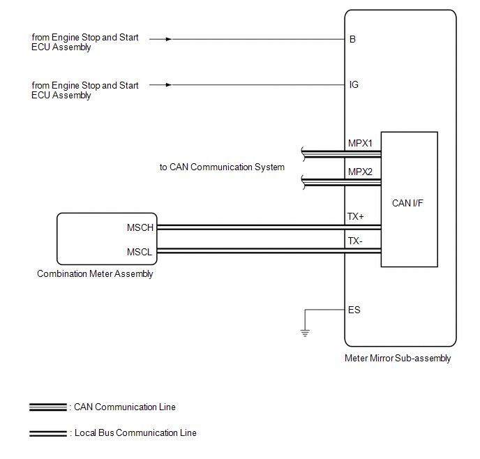
SYSTEM DIAGRAM
HINT:
Refer to System Diagram of CAN Communication System.
Click here

 Parts Location
P..
 How To Proceed With Troubleshooting
CAUTION / NOTICE / HINT HINT:
Use the following procedure to troubleshoot the headup display system.
*: Use the GTS.
PROCEDURE 1. VEHICLE BROUGHT TO WORKSHOP
NEXT
2...
Other information:
Toyota Yaris XP210 (2020-2026) Owner's Manual: Fuse Panel Description
F..
Toyota Yaris XP210 (2020-2026) Reapir and Service Manual: Components
COMPONENTS ILLUSTRATION *1 KNOCK SENSOR *2 NO. 1 VENTILATION CASE *3 NO. 2 CYLINDER BLOCK INSULATOR *4 NO. 2 WATER BY-PASS PIPE *5 NO. 6 WATER BY-PASS HOSE *6 NO. 4 WATER BY-PASS HOSE *7 GASKET - - N*m (kgf*cm, ft...
Categories
- Manuals Home
- Toyota Yaris Owners Manual
- Toyota Yaris Service Manual
- Removal
- How to connect USB port/Auxiliary jack
- Opening and Closing the Liftgate/Trunk Lid
- New on site
- Most important about car
Turning the Engine Off
Stop the vehicle completely. Manual transaxle: Shift into neutral and set the parking brake.Automatic transaxle: Shift the selector lever to the P position and set the parking brake.
Press the push button start to turn off the engine. The ignition position is off.
Copyright © 2026 www.toyaris4.com