Toyota Yaris: Mirror (ext) / Outer Rear View Mirror Glass
Components
COMPONENTS
ILLUSTRATION
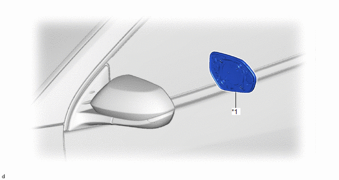
| *1 | OUTER MIRROR | - | - |
Removal
REMOVAL
CAUTION / NOTICE / HINT
HINT:
- Use the same procedure for the RH side and LH side.
- The following procedure is for the LH side.
PROCEDURE
1. REMOVE OUTER MIRROR
(a) Apply protective tape to the area as shown in the illustration.
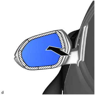
.png) | Push |
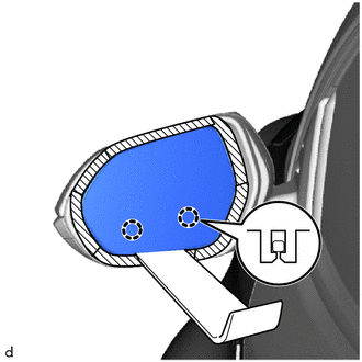
(b) Push the upper part of the mirror surface and tilt it.
NOTICE:
Do not push the outer mirror with excessive force. Doing so may cause the actuator to come off or break the mirror surface.
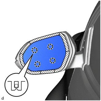
| (c) Using a moulding remover D, disengage the claws on the lower part of the outer mirror. |
|
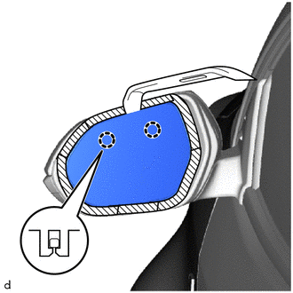
(d) Push the lower part of the mirror surface and tilt it.
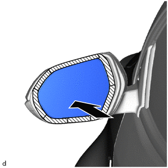
.png) | Push |
NOTICE:
Do not push the outer mirror with excessive force. Doing so may cause the actuator to come off or break the mirror surface.
HINT:
If excessive force is used when pressing down the mirror surface, the claws will engage again.
| (e) Using a moulding remover A, disengage the claws on the upper part of the outer mirror to remove the outer mirror. |
|
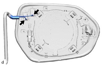
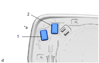
| (f) Disconnect the 2 connectors. |
|
Inspection
INSPECTION
PROCEDURE
1. INSPECT MIRROR OUTER LH
(a) Check the operation of the mirror heater.
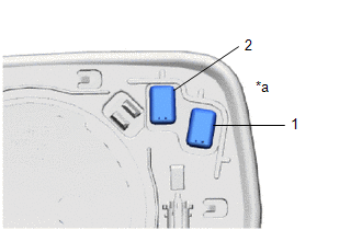
| (1) Measure the resistance according to the value(s) in the table below. Standard Resistance:
If the result is not as specified, replace the outer mirror LH. |
|
2. INSPECT OUTER MIRROR RH
(a) Check the operation of the mirror heater.
| (1) Measure the resistance according to the value(s) in the table below. Standard Resistance:
If the result is not as specified, replace the outer mirror RH. |
|
Installation
INSTALLATION
CAUTION / NOTICE / HINT
HINT:
- Use the same procedure for the RH side and LH side.
- The following procedure is for the LH side.
PROCEDURE
1. INSTALL OUTER MIRROR
(a) Connect the 2 connectors.
| (b) Engage the claws to install the outer mirror. NOTICE: Do not push the outer mirror with excessive force. Doing so may break the mirror surface. |
|
 Outer Rear View Mirror Cover
ComponentsCOMPONENTS ILLUSTRATION
*1 OUTER MIRROR *2 OUTER MIRROR COVER RemovalREMOVAL CAUTION / NOTICE / HINT HINT:
Use the same procedure for the RH side and LH side...
Other information:
Toyota Yaris XP210 (2020-2026) Reapir and Service Manual: Installation
INSTALLATION PROCEDURE 1. INSTALL OIL PRESSURE AND TEMPERATURE SENSOR (a) Apply adhesive to 2 or 3 threads of the oil pressure and temperature sensor. Adhesive: Toyota Genuine Adhesive 1344, Three Bond 1344 or equivalent NOTICE: Do not apply adhesive to the oil inlet port of the oil pressure and temperature sensor...
Toyota Yaris XP210 (2020-2026) Owner's Manual: Drive Selection
Drive Selection (Automatic Transaxle) Drive selection is a system to switch the vehicle’s drive mode. When the sport mode is selected, vehicle’s response against accelerator operation is enhanced. This provides additional quick acceleration which may be needed to safely make maneuvers such as lane changes, merging onto free ways, or passing other vehicles...
Categories
- Manuals Home
- Toyota Yaris Owners Manual
- Toyota Yaris Service Manual
- Maintenance
- Removal
- Immobilizer System
- New on site
- Most important about car
Key Suspend Function
If a key is left in the vehicle, the functions of the key left in the vehicle are temporarily suspended to prevent theft of the vehicle.
To restore the functions, press the unlock button on the functions-suspended key in the vehicle.

