Toyota Yaris: Manual Transaxle Assembly / Installation
INSTALLATION
PROCEDURE
1. INSTALL TRANSFER AND TRANSAXLE SETTING STUD BOLT
(a) Clean the bolt holes.
(b) Apply adhesive 1324 to 2 or 3 threads on one half of a new transfer and transaxle setting stud bolt A as shown in the illustration.
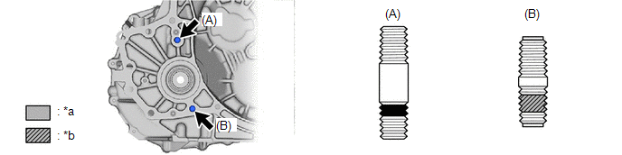
| *a | Toyota Genuine Adhesive 1324 | *b | Sealant |
Adhesive:
Toyota Genuine Adhesive 1324, Three Bond 1324 or equivalent
NOTICE:
- Do not apply adhesive 1324 to the ends of the transfer and transaxle setting stud bolt A.
- Install the transfer and transaxle setting stud bolt A immediately after applying adhesive to prevent the adherence of foreign matter.
(c) Install the transfer and transaxle setting stud bolt A to the manual transaxle assembly position shown in the illustration.
Torque:
39.2 N·m {400 kgf·cm, 29 ft·lbf}
NOTICE:
Install the transfer and transaxle setting stud bolt A so that the side that has adhesive is facing the manual transaxle assembly.
(d) Install a new transfer and transaxle setting stud bolt B to the manual transaxle assembly position shown in the illustration.
Torque:
39.2 N·m {400 kgf·cm, 29 ft·lbf}
NOTICE:
Install the transfer and transaxle setting stud bolt B so that the side that has sealant is facing the manual transaxle assembly.
2. INSTALL MANUAL TRANSMISSION CASE PLUG
(a) Coat a new O-ring with gear oil and install it to the manual transmission case plug.
(b) Install the manual transmission case plug to the manual transaxle assembly.
3. INSTALL WIRE HARNESS CLAMP BRACKET
(a) Install the wire harness clamp bracket to the manual transaxle assembly with the bolt.
Torque:
10 N·m {102 kgf·cm, 7 ft·lbf}
(b) Install the 2 wire harness clamp bracket to the manual transaxle assembly with the 2 bolts.
Torque:
10 N·m {102 kgf·cm, 7 ft·lbf}
4. INSTALL EXHAUST PIPE SUPPORT STAY
(a) Install the exhaust pipe support stay to the manual transaxle assembly with the 2 bolts.
Torque:
43 N·m {438 kgf·cm, 32 ft·lbf}
5. INSTALL CLUTCH FLEXIBLE HOSE BRACKET
(a) Install the clutch flexible hose bracket to the manual transaxle assembly with the bolt.
Torque:
19 N·m {194 kgf·cm, 14 ft·lbf}
6. INSTALL CLUTCH RELEASE CYLINDER WITH BEARING ASSEMBLY
Click here

7. INSTALL CLUTCH RELEASE BEARING PLATE
Click here

8. REMOVE CLUTCH RELEASE BLEEDER SUB-ASSEMBLY
Click here

9. INSPECT CLUTCH PIPE LINE
Click here

10. INSTALL CLUTCH RELEASE BLEEDER SUB-ASSEMBLY
Click here

11. INSTALL BLEEDER CLUTCH RELEASE TUBE
Click here

12. TEMPORARILY TIGHTEN TRANSFER ASSEMBLY
| (a) Temporarily install the transfer assembly to the manual transaxle assembly with the 4 nuts. |
|
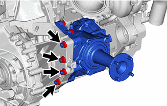
| (b) Temporarily install the 2 bolts and 2 nuts. |
|
13. INSTALL MANUAL TRANSAXLE ASSEMBLY
(a) Check that the 2 knock pins are installed on the engine assembly before installing the manual transaxle assembly.
(b) Align the input shaft with the clutch disc and install the manual transaxle assembly to the engine assembly.
NOTICE:
- Make sure that the wire harness or similar items are not pinched between the contact surfaces.
- Do not forcibly pry on the manual transaxle assembly when installing it to the engine assembly.
- Do not apply excessive force to the manual transaxle assembly as this will break the input shaft.
- Make sure that the knock pins fit securely into the holes when installing the manual transaxle assembly to the engine assembly.
- Make sure that the contact surfaces of the engine assembly and manual transaxle assembly are flat against each other before tightening the bolts.
(c) Install the 7 bolts in the order shown in the illustration.
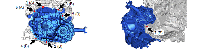
Torque:
for Bolt A :
64 N·m {653 kgf·cm, 47 ft·lbf}
for Bolt B :
46 N·m {469 kgf·cm, 34 ft·lbf}
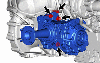
14. FULLY TIGHTEN TRANSFER ASSEMBLY
(a) Using SST and 17 mm union nut wrench, fully tighten the transfer assembly with the 2 bolts and 6 nuts.
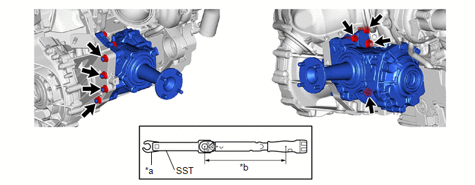
| *a | Union Nut Wrench | *b | Torque Wrench Fulcrum Length |
SST: 09961-00950
Torque:
Specified Tightening Torque :
68.6 N·m {700 kgf·cm, 51 ft·lbf}
HINT:
-
Calculate the torque wrench reading when changing the fulcrum length of the torque wrench.
Click here

- When using a union nut wrench (fulcrum length of 30 mm (1.18 in.)) + SST (fulcrum length of 150 mm (5.91 in.)) + torque wrench (fulcrum length of 255 mm (10.0 in.)): 40.2 N*m (410 kgf*cm, 30 ft.*lbf)
15. INSTALL PROPELLER SHAFT HEAT INSULATOR
(a) Install the propeller shaft heat insulator to the manual transaxle assembly and transfer assembly with the 2 bolts.
Torque:
25 N·m {255 kgf·cm, 18 ft·lbf}
16. INSTALL NO. 2 ENGINE MOVING CONTROL ROD
(a) Install the No. 2 engine moving control rod to the manual transaxle assembly with the 4 bolts.
Torque:
44 N·m {449 kgf·cm, 32 ft·lbf}
17. INSTALL FRONT SUSPENSION CROSSMEMBER SUB-ASSEMBLY
(a) Install the front suspension crossmember sub-assembly to the No. 2 engine moving control rod with the bolt.
Torque:
170 N·m {1734 kgf·cm, 125 ft·lbf}
18. INSTALL TURBINE OUTLET ELBOW GASKET
Click here

19. INSTALL EXHAUST MANIFOLD CONVERTER SUB-ASSEMBLY
Click here

20. CONNECT ENGINE WIRE
| (a) Engage the 2 clamps to install the engine wire to the wire harness clamp bracket. |
|
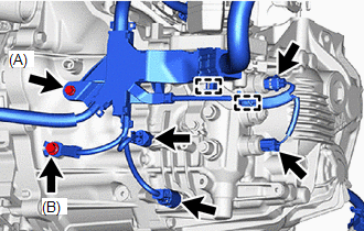
(b) Install the engine wire to the manual transaxle assembly with the 2 bolts.
Torque:
for Bolt A :
10 N·m {102 kgf·cm, 7 ft·lbf}
for Bolt B :
20 N·m {204 kgf·cm, 15 ft·lbf}
(c) Connect the 4 connectors.
(d) Engage the 2 clamps to install the engine wire to the wire harness clamp bracket.
(e) Install the engine wire to the wire harness clamp bracket with the bolt.
Torque:
10 N·m {102 kgf·cm, 7 ft·lbf}
(f) Connect the connector
(g) Engage the 4 clamps to install the engine wire to the wire harness clamp bracket.
21. INSTALL STARTER ASSEMBLY
Click here

22. INSTALL FLYWHEEL HOUSING SIDE COVER
Click here

23. INSTALL ENGINE ASSEMBLY WITH TRANSAXLE
Click here

24. ADJUST TRANSMISSION CONTROL CABLE ASSEMBLY
Click here

 Removal
REMOVAL CAUTION / NOTICE / HINT The necessary procedures (adjustment, calibration, initialization, or registration) that must be performed after parts are removed and installed, or replaced during the manual transaxle assembly removal/installation are shown below...
 Manual Transaxle Oil
ComponentsCOMPONENTS ILLUSTRATION
*1 NO. 1 ENGINE UNDER COVER ASSEMBLY *2 ENGINE UNDER COVER LH *3 MANUAL TRANSMISSION FILLER PLUG *4 MANUAL TRANSMISSION DRAIN PLUG *5 GASKET - -
N*m (kgf*cm, ft...
Other information:
Toyota Yaris XP210 (2020-2026) Reapir and Service Manual: Reassembly
REASSEMBLY PROCEDURE 1. INSTALL HOOD BUMPER CUSHION (a) Rotate clockwise to install the 2 hood bumper cushions. 2. INSTALL HOOD SUPPORT ASSEMBLY (a) Engage the claws to install the hood support assembly. 3. INSTALL HOOD STAY HOLDER (a) Engage the claws to install the hood stay holder...
Toyota Yaris XP210 (2020-2026) Reapir and Service Manual: Components
COMPONENTS ILLUSTRATION *1 FRONT SEAT HEADREST ASSEMBLY *2 FRONT OUTER SEAT TRACK BRACKET COVER *3 FRONT INNER SEAT TRACK BRACKET COVER *4 OUTER SEAT TRACK BRACKET COVER *5 INNER SEAT TRACK BRACKET COVER *6 FRONT SEAT ASSEMBLY Tightening torque for "Major areas involving basic vehicle performance such as moving/turning/stopping" : N*m (kgf*cm, ft...
Categories
- Manuals Home
- Toyota Yaris Owners Manual
- Toyota Yaris Service Manual
- To Set Speed
- How to use USB mode
- Adjustment
- New on site
- Most important about car
Supplemental Restraint System (SRS) Precautions
The front and side supplemental restraint systems (SRS) include different types of air bags. Please verify the different types of air bags which are equipped on your vehicle by locating the “SRS AIRBAG” location indicators. These indicators are visible in the area where the air bags are installed.
The air bags are installed in the following locations:
The steering wheel hub (driver air bag) The front passenger dashboard (front passenger air bag) The outboard sides of the front seatbacks (side air bags) The front and rear window pillars, and the roof edge along both sides (curtain air bags)