Toyota Yaris: Front Brake Flexible Hose / Installation
INSTALLATION
CAUTION / NOTICE / HINT
NOTICE:
- Because the left and right front flexible hoses are not interchangeable, verify the part number when installing the front flexible hoses.
- When reusing the front flexible hoses, use the identification marks created during removal to install each front flexible hose to its original position.
HINT:
- Use the same procedure for the RH side and LH side.
- The following procedure is for the LH side.
PROCEDURE
1. INSTALL FRONT FLEXIBLE HOSE
NOTICE:
When installing the front flexible hose, minimize twisting of the hose.
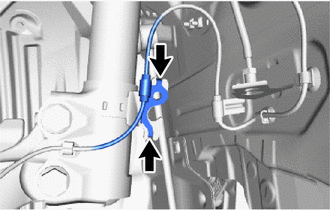
| (a) Install the front flexible hose with a new clip. NOTICE:
|
|
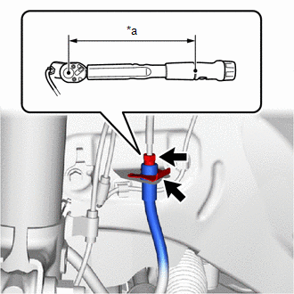
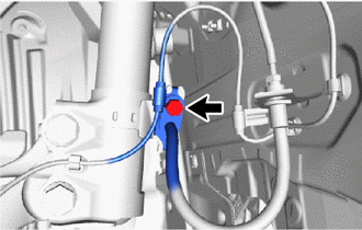
(b) Using a union nut wrench, connect the brake line to the front flexible hose while holding the front flexible hose with a wrench.
Torque:
Specified tightening torque :
15.2 N·m {155 kgf·cm, 11 ft·lbf}
NOTICE:
- Do not kink or damage the brake line.
- Do not allow any foreign matter such as dirt or dust to enter the brake line from the connecting parts.
HINT:
-
Calculate the torque wrench reading when changing the fulcrum length of the torque wrench.
Click here

-
When using a union nut wrench (fulcrum length of 22 mm (0.866 in.)) + torque wrench (fulcrum length of 162 mm (6.38 in.)):
13.4 N*m (137 kgf*cm, 10 ft.*lbf)
| (c) Engage the 2 hooks to install the front speed sensor clamp bracket. NOTICE: Do not twist the front speed sensor wire harness when installing it. |
|
| (d) Install the front flexible hose and front speed sensor to the front shock absorber assembly with the bolt. Torque: 29.4 N·m {300 kgf·cm, 22 ft·lbf} NOTICE: Do not twist the front flexible hose when installing it. |
|
(e) Connect the front flexible hose to the front disc brake cylinder assembly with a new union bolt and a new gasket.
Torque:
39.2 N·m {400 kgf·cm, 29 ft·lbf}
NOTICE:
- Install the front flexible hose lock securely into the lock hole in the front disc brake cylinder assembly.
- Do not twist the front flexible hose when installing it.
2. BLEED BRAKE LINE
Click here

3. INSTALL FRONT WHEEL
Click here

 Removal
REMOVAL CAUTION / NOTICE / HINT HINT:
Use the same procedure for the RH side and LH side.
The following procedure is for the LH side.
PROCEDURE 1...

Other information:
Toyota Yaris XP210 (2020-2026) Reapir and Service Manual: Vehicle Control History
VEHICLE CONTROL HISTORY CHECK VEHICLE CONTROL HISTORY HINT: The vehicle control history data stores the history of the reject function and system protection operations. The number of occurrences, date and distance are stored in batches for each item...
Toyota Yaris XP210 (2020-2026) Reapir and Service Manual: Utility
UTILITY Front Beam Axis Adjustment HINT: Front Beam Axis Adjustment is used to calibrate the beam axis of millimeter wave radar sensor assembly. (a) Perform Front Beam Axis Adjustment according to the display on the GTS. Body Electrical > Front Radar Sensor > Utility Tester Display Front Beam Axis Adjustment Front Beam Axis Misalignment Reading HINT: Front Beam Axis Misalignment Reading is used to check the amount of misalignment of the millimeter wave radar sensor assembly...
Categories
- Manuals Home
- Toyota Yaris Owners Manual
- Toyota Yaris Service Manual
- Fuse Panel Description
- G16e-gts (engine Mechanical)
- How to use USB mode
- New on site
- Most important about car
Fuel-Filler Lid and Cap
WARNING
When removing the fuel-filler cap, loosen the cap slightly and wait for any hissing to stop, then remove it
Fuel spray is dangerous. Fuel can burn skin and eyes and cause illness if ingested. Fuel spray is released when there is pressure in the fuel tank and the fuel-filler cap is removed too quickly.