
Toyota Yaris: Occupant Detection Sensor / Installation
INSTALLATION
CAUTION / NOTICE / HINT
CAUTION:
Wear protective gloves. Sharp areas on the parts may injure your hands.
PROCEDURE
1. INSTALL OCCUPANT DETECTION SENSOR (SEPARATE TYPE FRONT SEAT CUSHION PAD)
NOTICE:
When installing a separate type front seat cushion cover, refer to Precaution in order to prevent wrinkles from forming.
Click here

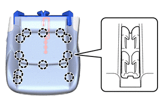
(a) for Sporty Seat Type:
| (1) Engage the claws to install the occupant detection sensor (separate type front seat cushion pad) to the separate type front seat cushion cover. |
|
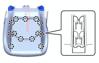
(b) for Sports Seat Type:
| (1) Engage the claws to install the occupant detection sensor (separate type front seat cushion pad) to the separate type front seat cushion cover. |
|
2. INSTALL CONNECTOR HOLDER
Click here

3. INSTALL SEPARATE TYPE FRONT SEAT CUSHION COVER WITH PAD
HINT:
Use the same procedure as for the driver side.
Click here

4. INSTALL SEPARATE TYPE FRONT SEATBACK ASSEMBLY
HINT:
Use the same procedure as for the driver side.
Click here

5. INSTALL FRONT SEAT INNER CUSHION SHIELD
Click here

6. INSTALL FRONT SEAT CUSHION SHIELD
Click here

7. INSTALL RECLINING ADJUSTER RELEASE HANDLE
HINT:
Use the same procedure as for the driver side.
Click here

8. INSTALL SEPARATE TYPE FRONT SEAT CUSHION PAD
HINT:
Use the same procedure as for the driver side.
Click here

9. INSTALL FRONT SEAT INNER BELT ASSEMBLY
Click here

10. INSTALL FRONT SEAT ASSEMBLY
HINT:
Use the same procedure as for the driver side.
Click here

 Inspection
INSPECTION PROCEDURE 1. INSPECT OCCUPANT DETECTION SENSOR (SEPARATE TYPE FRONT SEAT CUSHION PAD) (a) Check the resistance. (1) Measure the resistance according to the value(s) in the table below...

Other information:
Toyota Yaris XP210 (2020-2026) Owner's Manual: Warning Lights
These lights turn on or flash to notify the user of the system operation status or a system malfunction. Master Warning Light Brake System Warning Light ABS Warning Light Charging System Warning Light Engine Oil Warning Light Check Engine Light High Engine Coolant Temperature Warning Light Automatic Transaxle Warning Light Power Steering Malfunction Indicator Light Air Bag/Front Seat Belt Pretensioner System Warning Light LED Headlight Warning Light Low Fuel Warning Light Check Fuel Cap Warning Light Seat Belt Warning Light (Front seat) Door-Ajar Warning Light Low Washer Fluid Level Warning Light Tire Pressure Monitoring System Warning Light KEY Warning Light Low Speed Pre-Collision System Warning Light * 1: The light turns on when the ignition is switched on for an operation check, and turns off a few seconds later or when the engine is started...
Toyota Yaris XP210 (2020-2026) Reapir and Service Manual: Problem Symptoms Table
PROBLEM SYMPTOMS TABLE NOTICE: If the main body ECU (multiplex network body ECU) is replaced, refer to the Registration. Click here HINT: Troubleshooting of the theft deterrent system is based on the premise that the power door lock control system and the wireless door lock control system are operating normally...
Categories
- Manuals Home
- Toyota Yaris Owners Manual
- Toyota Yaris Service Manual
- Immobilizer System
- Engine & Hybrid System
- Engine Start Function When Key Battery is Dead
- New on site
- Most important about car
Front Seat Belt Pretensioners
The front seat belt pretensioners are designed to deploy in moderate or severe frontal, near frontal collisions.
In addition, the pretensioners operate when a side collision or a rollover accident is detected. The pretensioners operate differently depending on what types of air bags are equipped. For more details about the seat belt pretensioner operation, refer to the SRS Air Bag Deployment Criteria.
