Toyota Yaris: Engine Coolant Temperature Sensor / Installation
INSTALLATION
PROCEDURE
1. INSTALL ENGINE COOLANT TEMPERATURE SENSOR
HINT:
Perform "Inspection After Repair" after replacing the engine coolant temperature sensor.
Click here

| (a) Apply a light coat of engine coolant to the O-ring of the engine coolant temperature sensor. |
|
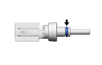
| (b) Install the engine coolant temperature sensor to the water outlet with a new clip. NOTICE:
|
|
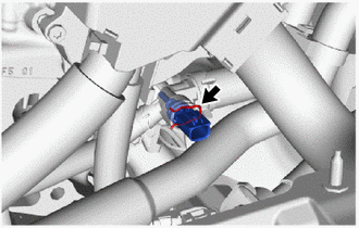
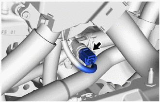
| (c) Connect the engine coolant temperature sensor connector. |
|
2. ADD ENGINE COOLANT
Click here

3. INSPECT FOR COOLANT LEAK
Click here

4. INSTALL NO. 1 ENGINE UNDER COVER ASSEMBLY
Click here

5. PERFORM INITIALIZATION
(a) Perform "Inspection After Repair" after replacing the engine coolant temperature sensor.
Click here

 Removal
REMOVAL CAUTION / NOTICE / HINT The necessary procedures (adjustment, calibration, initialization or registration) that must be performed after parts are removed and installed, or replaced during radiator assembly removal/installation are shown below...
 Ignition Coil And Spark Plug
ComponentsCOMPONENTS ILLUSTRATION
*1 SPARK PLUG *2 IGNITION COIL ASSEMBLY
N*m (kgf*cm, ft.*lbf): Specified torque - - RemovalREMOVAL CAUTION / NOTICE / HINT The necessary procedures (adjustment, calibration, initialization or registration) that must be performed after parts are removed and installed, or replaced during ignition coil assembly or spark plug removal/installation are shown below...
Other information:
Toyota Yaris XP210 (2020-2026) Reapir and Service Manual: Data List / Active Test
DATA LIST / ACTIVE TEST DATA LIST NOTICE: In the following table, the values listed under "Normal Condition" are reference values. Do not depend solely on these reference values when deciding whether a part is faulty or not. HINT: Using the GTS to read the Data List allows the values or states of switches, sensors, actuators and other items to be read without removing any parts...
Toyota Yaris XP210 (2020-2026) Owner's Manual: Bluetooth® Hands-Free
Phonebook Usage Telephone calls can be made by saying the contact name in the downloaded phonebook or the name of a person whose phone number has been registered in the Bluetooth® Hands-Free. Refer to Import contact (Download Phonebook). Press the talk button...
Categories
- Manuals Home
- Toyota Yaris Owners Manual
- Toyota Yaris Service Manual
- How to connect USB port/Auxiliary jack
- Power Integration No.1 System Missing Message (B235287,B235587,B235787-B235987)
- Maintenance
- New on site
- Most important about car
Front Seat Belt Pretensioners
The front seat belt pretensioners are designed to deploy in moderate or severe frontal, near frontal collisions.
In addition, the pretensioners operate when a side collision or a rollover accident is detected. The pretensioners operate differently depending on what types of air bags are equipped. For more details about the seat belt pretensioner operation, refer to the SRS Air Bag Deployment Criteria.