Toyota Yaris: Front Seat Cushion Heater / Inspection
INSPECTION
PROCEDURE
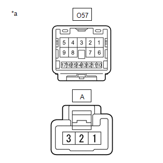
1. INSPECT FRONT SEAT CUSHION HEATER ASSEMBLY LH
| (a) Check the resistance. (1) Measure the resistance according to the value(s) in the table below. Standard Resistance:
|
| |||||||||||||||||||
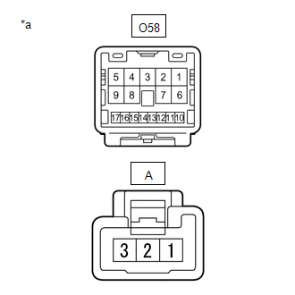
2. INSPECT FRONT SEAT CUSHION HEATER ASSEMBLY RH
| (a) Check the resistance. (1) Measure the resistance according to the value(s) in the table below. Standard Resistance:
|
| |||||||||||||||||||
 Removal
REMOVAL CAUTION / NOTICE / HINT CAUTION: Wear protective gloves. Sharp areas on the parts may injure your hands.
HINT:
When the cable is disconnected / reconnected to the auxiliary battery terminal, systems temporarily stop operating...
 Installation
INSTALLATION CAUTION / NOTICE / HINT CAUTION: Wear protective gloves. Sharp areas on the parts may injure your hands. HINT:
Use the same procedure for the driver side and front passenger side...
Other information:
Toyota Yaris XP210 (2020-2026) Reapir and Service Manual: Installation
INSTALLATION PROCEDURE 1. INSTALL AIR CONDITIONER PRESSURE SENSOR (a) Remove the vinyl tape from the No. 2 air conditioner tube and accessory assembly. (b) Sufficiently apply compressor oil to a new air conditioner pressure sensor and the fitting surface of the air conditioner pressure sensor...
Toyota Yaris XP210 (2020-2026) Reapir and Service Manual: Diagnostic Trouble Code Chart
D..
Categories
- Manuals Home
- Toyota Yaris Owners Manual
- Toyota Yaris Service Manual
- G16e-gts (engine Mechanical)
- Engine Start Function When Key Battery is Dead
- Headlights
- New on site
- Most important about car
Break-In Period
No special break-in is necessary, but a few precautions in the first 600 miles (1,000 km) may add to the performance, economy, and life of the vehicle.
Do not race the engine. Do not maintain one constant speed, either slow or fast, for a long period of time. Do not drive constantly at full-throttle or high engine rpm for extended periods of time. Avoid unnecessary hard stops. Avoid full-throttle starts.