Toyota Yaris: Front Stabilizer Bar / Inspection
INSPECTION
PROCEDURE
1. INSPECT FRONT STABILIZER LINK ASSEMBLY
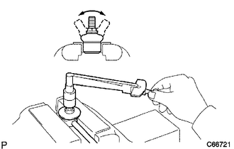
| (a) Inspect the turning torque of the ball joint. (1) Secure the front stabilizer link assembly in a vise using aluminum plates. NOTICE: Do not overtighten the vise. (2) Install the nut to the front stabilizer link assembly stud. (3) Using a torque wrench, turn the stud continuously at a rate of 3 to 5 seconds per turn and take the torque reading on the 5th turn. Turning Torque: 0.05 to 1.96 N*m (1 to 19 kgf*cm, 1 to 17 in.*lbf) HINT: If the turning torque is not within the specified range, replace the front stabilizer link assembly with a new one. (4) Turn the stud to check that the stud does not catch and there is no play HINT: If the stud catches or there is play while turning, replace the front stabilizer link assembly with a new one. |
|
(b) Inspect the dust cover.
(1) Check that the dust cover is not cracked and that there is no grease on it.
HINT:
If the dust cover is cracked or there is grease on it, replace the front stabilizer link assembly with a new one.
 Removal
REMOVAL CAUTION / NOTICE / HINT The necessary procedures (adjustment, calibration, initialization, or registration) that must be performed after parts are removed, installed, or replaced during the front stabilizer bar removal/installation are shown below...
 Installation
INSTALLATION PROCEDURE 1. INSTALL FRONT STABILIZER BAR (a) Set the front stabilizer bar to the front suspension crossmember sub-assembly. NOTICE: Make sure that the identification mark is positioned on the right side of the vehicle...
Other information:
Toyota Yaris XP210 (2020-2026) Reapir and Service Manual: Pre-ignition Detected (P137800)
DESCRIPTION If sudden early ignition (pre-ignition) occurs continuously in a short period of time, a DTC is stored. This pre-ignition is a phenomenon inherent in boosted engines. Atomized engine oil and detached deposits (carbon) cause ignition and promote knocking during low-speed, high-output operation...
Toyota Yaris XP210 (2020-2026) Reapir and Service Manual: Components
COMPONENTS ILLUSTRATION *1 FRONT BUMPER ASSEMBLY *2 PIN HOLD CLIP ILLUSTRATION *A w/ Pre-collision System - - *1 NO. 3 ENGINE ROOM WIRE *2 MILLIMETER WAVE RADAR SENSOR ASSEMBLY N*m (kgf*cm, ft.*lbf): Specified torque - - ILLUSTRATION *1 FOG LIGHT COVER LH *2 FOG LIGHT COVER RH *3 FOG LIGHT ASSEMBLY LH *4 FOG LIGHT ASSEMBLY RH *5 FRONT BUMPER HOLE COVER *6 HOOD TO FRONT END PANEL SEAL *7 LOWER RADIATOR GRILLE SUB-ASSEMBLY *8 RADIATOR GRILLE SIDE MOULDING LH *9 RADIATOR GRILLE SIDE MOULDING RH *10 RADIATOR GRILLE EMBLEM ASSEMBLY *11 FRONT BUMPER EXTENSION MOUNTING BRACKET - - ILLUSTRATION *1 FRONT BUMPER ENERGY ABSORBER *2 FRONT BUMPER SIDE RETAINER RH *3 RADIATOR UPPER AIR GUIDE PLATE *4 HEADLIGHT ASSEMBLY RH *5 HEADLIGHT ASSEMBLY LH *6 FRONT BUMPER SIDE RETAINER LH *7 FRONT BUMPER REINFORCEMENT *8 THERMISTOR ASSEMBLY *9 COOL AIR INTAKE DUCT - - N*m (kgf*cm, ft...
Categories
- Manuals Home
- Toyota Yaris Owners Manual
- Toyota Yaris Service Manual
- How to connect USB port/Auxiliary jack
- Engine & Hybrid System
- Battery Monitor Module General Electrical Failure (P058A01)
- New on site
- Most important about car
Refueling
Before refueling, close all the doors, windows, and the liftgate/trunk lid, and switch the ignition OFF.
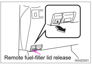
To open the fuel-filler lid, pull the remote fuel-filler lid release.