Toyota Yaris: Front Stabilizer Bar / Removal
REMOVAL
CAUTION / NOTICE / HINT
The necessary procedures (adjustment, calibration, initialization, or registration) that must be performed after parts are removed, installed, or replaced during the front stabilizer bar removal/installation are shown below.
Necessary Procedure After Parts Removed/Installed/Replaced| Replacement Part or Procedure | Necessary Procedure | Effect/Inoperative when not Performed | Link |
|---|---|---|---|
| Front wheel alignment adjustment | ECU Data Initialization | Active torque split AWD system |
|
| Calibration |
|
|


PROCEDURE
1. REMOVE STEERING LINK ASSEMBLY
Click here

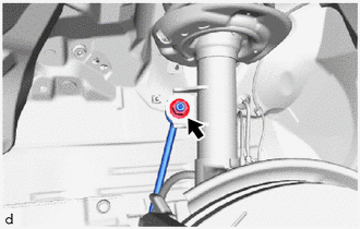
2. REMOVE FRONT STABILIZER LINK ASSEMBLY LH
| (a) Remove the nut and front stabilizer link assembly LH from the front shock absorber assembly. NOTICE: Do not damage the boot of the ball joint. HINT: If the ball joint turns together with the nut, use a 6 mm hexagon socket wrench to hold the stud bolt. |
|
3. REMOVE FRONT STABILIZER LINK ASSEMBLY RH
HINT:
Perform the same procedure as for the LH side.
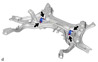
4. REMOVE FRONT STABILIZER BAR
| (a) Remove the 4 bolts and front stabilizer bar from the front suspension crossmember sub-assembly. |
|
 Components
COMPONENTS ILLUSTRATION
*1 FRONT STABILIZER BAR *2 FRONT STABILIZER LINK ASSEMBLY LH *3 FRONT STABILIZER LINK ASSEMBLY RH - -
Tightening torque for "Major areas involving basic vehicle performance such as moving/turning/stopping" : N*m (kgf*cm, ft...
 Inspection
INSPECTION PROCEDURE 1. INSPECT FRONT STABILIZER LINK ASSEMBLY (a) Inspect the turning torque of the ball joint. (1) Secure the front stabilizer link assembly in a vise using aluminum plates...
Other information:
Toyota Yaris XP210 (2020-2026) Reapir and Service Manual: Components
COMPONENTS ILLUSTRATION *1 PORT FUEL INJECTOR ASSEMBLY *2 NO. 5 ENGINE WIRE *3 INJECTOR VIBRATION INSULATOR *4 FUEL DELIVERY SPACER *5 FUEL DELIVERY PIPE *6 FUEL DELIVERY GUARD *7 OIL LEVEL GAUGE GUIDE *8 OIL LEVEL GAUGE SUB-ASSEMBLY *9 NO...
Toyota Yaris XP210 (2020-2026) Reapir and Service Manual: Installation
INSTALLATION PROCEDURE 1. INSTALL NO. 2 TURBO PRESSURE SENSOR (a) Install the No. 2 turbo pressure sensor to the air tube assembly with the 2 bolts. NOTICE: If the No. 2 turbo pressure sensor has been struck or dropped, replace it. Torque: 10 N·m {102 kgf·cm, 7 ft·lbf} (b) Connect the No...
Categories
- Manuals Home
- Toyota Yaris Owners Manual
- Toyota Yaris Service Manual
- How to connect USB port/Auxiliary jack
- Adjustment
- To Set Speed
- New on site
- Most important about car
Liftgate/Trunk Lid
WARNING
Never allow a person to ride in the luggage compartment/trunk
Allowing a person to ride in the luggage compartment/trunk is dangerous. The person in the luggage compartment/trunk could be seriously injured or killed during sudden braking or a collision.
Do not drive with the liftgate/trunk lid open