Toyota Yaris: Fuel Pressure Sensor / Inspection
INSPECTION
PROCEDURE
1. INSPECT NO. 2 FUEL PRESSURE SENSOR
(a) Check the No. 2 fuel pressure sensor output voltage.
| (1) Apply 5 V between terminals 1 (VC) and 3 (E2). NOTICE:
HINT: If a stable power supply is not available, connect 4 nickel-metal hydride batteries (1.2 V each) or equivalent in series. |
|
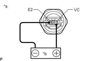
| (2) Measure the voltage according to the value(s) in the table below. Standard Voltage:
*: The output voltage changes depending on the voltage applied to the terminals. If the result is not as specified, replace the No. 2 fuel pressure sensor. |
|
 Removal
REMOVAL CAUTION / NOTICE / HINT The necessary procedures (adjustment, calibration, initialization or registration) that must be performed after parts are removed and installed, or replaced during No...
 Installation
INSTALLATION CAUTION / NOTICE / HINT NOTICE: This procedure includes the installation of small-head bolts. Refer to Small-Head Bolts of Basic Repair Hint to identify the small-head bolts...
Other information:
Toyota Yaris XP210 (2020-2026) Reapir and Service Manual: Inspection
INSPECTION PROCEDURE 1. INSPECT STOP LIGHT LED (for LH Side) (a) Check that the stop light LED. (1) Apply auxiliary battery voltage to the stop light LED and check that the light comes on. OK: Condition Specified Condition O109-3 (B) - Auxiliary battery positive (+) O109-1 (E) - Auxiliary battery negative (-) Stop light LED comes on If the result is not as specified, replace the stop light LED...
Toyota Yaris XP210 (2020-2026) Owner's Manual: Fog Lights
Use this switch to turn on the fog lights. The fog lights will improve visibility at night and during foggy conditions. The fog lights can be used when the ignition is switched ON. The fog lights turn on when the fog light switch is turned to the position and turn off when the switch is turned to the OFF position...
Categories
- Manuals Home
- Toyota Yaris Owners Manual
- Toyota Yaris Service Manual
- Fuel Gauge
- Brake System Control Module "A" System Voltage System Voltage Low (C137BA2)
- To Set Speed
- New on site
- Most important about car
Liftgate/Trunk Lid
WARNING
Never allow a person to ride in the luggage compartment/trunk
Allowing a person to ride in the luggage compartment/trunk is dangerous. The person in the luggage compartment/trunk could be seriously injured or killed during sudden braking or a collision.
Do not drive with the liftgate/trunk lid open