Toyota Yaris: Meter / Gauge / Display / Headup Display
Components
COMPONENTS
ILLUSTRATION
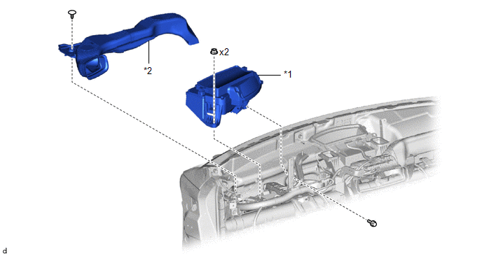
| *1 | METER MIRROR SUB-ASSEMBLY | *2 | NO. 1 HEATER TO REGISTER DUCT SUB-ASSEMBLY |
Removal
REMOVAL
CAUTION / NOTICE / HINT
HINT:
When the cable is disconnected/reconnected to the auxiliary battery terminal, systems temporarily stop operating. However, each system has a function that completes learning the first time the system is used.
-
Learning completes when vehicle is driven
Effect/Inoperative Function When Necessary Procedures are not Performed
Necessary Procedures
Link
Lane tracing assist system
Drive the vehicle straight ahead at 35 km/h (22 mph) or more for 5 second or more.

Pre-collision system
Stop and start system
Drive the vehicle until stop and start control is permitted (approximately 5 to 60 minutes)

-
Learning completes when vehicle is operated normally
Effect/Inoperative Function When Necessary Procedures are not Performed
Necessary Procedures
Link
Pre-collision system
- Back door opener
Perform door unlock operation with door control switch or electrical key transmitter sub-assembly switch.

Air conditioning system
After the ignition switch is turned to ON, the servo motor standard position is recognized.
-
PROCEDURE
1. REMOVE INSTRUMENT PANEL SUB-ASSEMBLY
Click here

2. REMOVE NO. 1 HEATER TO REGISTER DUCT SUB-ASSEMBLY
Click here

3. REMOVE METER MIRROR SUB-ASSEMBLY
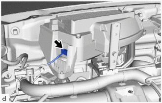
| (a) Disconnect the connector. |
|
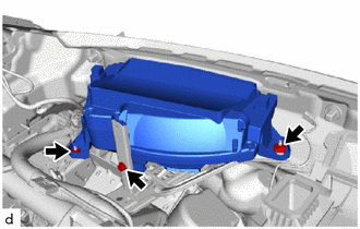
| (b) Remove the 2 nuts and bolt and meter mirror sub-assembly. |
|
Installation
INSTALLATION
PROCEDURE
1. INSTALL METER MIRROR SUB-ASSEMBLY
| (a) Temporarily install the meter mirror sub-assembly with the 2 nuts and bolt. |
|

(b) Tighten the 2 nuts and bolt in the order shown in the illustration.
(c) Connect the connector.
2. INSTALL NO. 1 HEATER TO REGISTER DUCT SUB-ASSEMBLY
Click here

3. INSTALL INSTRUMENT PANEL SUB-ASSEMBLY
Click here

 Installation
INSTALLATION PROCEDURE 1. INSTALL COMBINATION METER ASSEMBLY (a) Connect the 2 connectors. (b) Engage the guide and clips to install the combination meter assembly...

Other information:
Toyota Yaris XP210 (2020-2026) Reapir and Service Manual: Disassembly
DISASSEMBLY PROCEDURE 1. REMOVE MILLIMETER WAVE RADAR SENSOR ASSEMBLY (w/ Pre-collision System) Click here 2. REMOVE NO. 3 ENGINE ROOM WIRE (w/ Pre-collision System) (a) Disengage the clamps to remove the No. 3 engine room wire. 3. REMOVE FOG LIGHT ASSEMBLY LH Click here 4...
Toyota Yaris XP210 (2020-2026) Reapir and Service Manual: Components
C..
Categories
- Manuals Home
- Toyota Yaris Owners Manual
- Toyota Yaris Service Manual
- Key Battery Replacement
- G16e-gts (engine Mechanical)
- Removal
- New on site
- Most important about car
Fuel Gauge
The fuel gauge shows approximately how much fuel is remaining in the tank when the ignition is switched ON. We recommend keeping the tank over 1/4 full.
