
Toyota Yaris: Manual Transaxle System / Freeze Frame Data
FREEZE FRAME DATA
DESCRIPTION
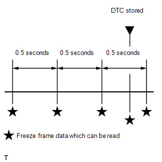
The ECM records vehicle and driving condition information as freeze frame data the moment a DTC is stored. When troubleshooting, freeze frame data can be helpful in determining whether the vehicle was moving or stationary, whether the engine was warmed up or not, whether the air fuel ratio was lean or rich, as well as other data recorded at the time of a malfunction.
HINT:
If it is impossible to replicate the problem even though a DTC is detected, confirm the freeze frame data.
The ECM records engine conditions in the form of freeze frame data every 0.5 seconds. Using the GTS, 5 separate sets of freeze frame data can be checked.
- 3 data sets before the DTC was stored.
- 1 data set when the DTC was stored.
- 1 data set after the DTC was stored.
These data sets can be used to simulate the condition of the vehicle around the time of the occurrence the malfunction. The data may assist in identifying the cause of the malfunction, and judging whether it was temporary or not.
LIST OF FREEZE FRAME DATA
Powertrain > Engine| Tester Display |
|---|
| Total Distance Traveled |
| Total Distance Traveled - Unit |
| Vehicle Speed |
| Engine Speed |
| Mass Air Flow Sensor |
| Intake Manifold Absolute Pressure |
| Intake Manifold Absolute Pressure Supported |
| Coolant Temperature |
| BATT Voltage |
| Throttle Motor Duty Ratio |
| Starter SW |
| Neutral Position SW |
| Stop Light SW |
| Cruise Main SW |
| NIM Sensor Speed |
| NIM Sensor Voltage |
| Shift SW Status (R Range) |
| Clutch Stroke Position |
| Clutch Stroke Sensor Voltage |
| M/T Oil Temperature |
| iMT SW |
| iMT Telltale |
 Dtc Check / Clear
DTC CHECK / CLEAR CHECK DTC (Using GTS) (a) DTCs which are stored in the ECM can be output to the GTS. (1) Connect the GTS to the DLC3. (2) Turn the ignition switch to ON...
 Data List / Active Test
DATA LIST / ACTIVE TEST DATA LIST NOTICE: In the table below, the values listed under "Normal Condition" are reference values. Do not depend solely on these reference values when deciding whether a part is faulty or not...
Other information:
Toyota Yaris XP210 (2020-2026) Reapir and Service Manual: Ambient Temperature Sensor Circuit Short to Ground (P007011)
DESCRIPTION The thermistor assembly is installed in front of the cooler condenser assembly to detect the ambient temperature, which is used to control the air conditioning system. This sensor is connected to the combination meter assembly and detects fluctuations in the ambient temperature...
Toyota Yaris XP210 (2020-2026) Owner's Manual: Interior Lights
Overhead Lights OFF DOOR ON Map Lights When the overhead light switch is in the door or off position, press the lens to illuminate the map lights, and then press the lens again to turn them off. Luggage Compartment Lights (5-Door) Trunk Light (4-Door) The trunk light is on when the lid is open and off when it’s closed...
Categories
- Manuals Home
- Toyota Yaris Owners Manual
- Toyota Yaris Service Manual
- Opening and Closing the Liftgate/Trunk Lid
- Adjustment
- Removal
- New on site
- Most important about car
Liftgate/Trunk Lid
WARNING
Never allow a person to ride in the luggage compartment/trunk
Allowing a person to ride in the luggage compartment/trunk is dangerous. The person in the luggage compartment/trunk could be seriously injured or killed during sudden braking or a collision.
Do not drive with the liftgate/trunk lid open
