Toyota Yaris: Stop And Start System / Crankshaft Position Sensor "A" Signal Compare Failure (P033562)
DESCRIPTION
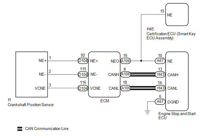
The crankshaft position sensor sends an engine speed signal (NE signal) to the ECM. The engine speed signal is then sent directly from the NEO terminal of the ECM to the engine stop and start ECU. Additionally, the ECM sends the engine speed to the engine stop and start ECU via CAN communication. The engine stop and start ECU compares the NE signal and engine speed received via CAN communication to check for errors in the NE signal.
If the NE signal is abnormal, the engine stop and start ECU will blink the stop and start cancel indicator and stores DTC P033562.
| DTC No. | Detection Item | DTC Detection Condition | Trouble Area | Warning Indicate | Memory | Note |
|---|---|---|---|---|---|---|
| P033562 | Crankshaft Position Sensor "A" Signal Compare Failure | All of the following conditions are met for 10 seconds (1 trip detection logic):
|
| Blinks | DTC stored | SAE Code: P0335 |
CONFIRMATION DRIVING PATTERN
CONFIRMATION AFTER TROUBLESHOOTING
HINT:
-
If the cable is disconnected from the auxiliary battery terminal, stop and start control is prohibited until refresh charge is completed.
In this case, let the vehicle idle to complete the refresh charge. The refresh charge is complete when the Data List item Status of Auxiliary battery Charge Control changes Bes from "Refresh Charge Mode". (Usually, idling the engine for 5 to 60 minutes with the auxiliary battery fluid temperature at 11°C (52°F) or higher, the refresh charge will be completed.)
-
If the GTS is not available and the Data List item Status of Auxiliary Battery Charge Control cannot be checked, charge the auxiliary battery by idling the engine for approximately 5 to 60 minutes or driving the vehicle, and then drive the vehicle and check that stop and start control operates.
If the engine is started with the hood open, the system determines that a jump start has occurred. Therefore, make sure that the hood is closed before starting the engine and driving the vehicle.
- After the refresh charge completes, turn the ignition switch off, wait for at least 30 seconds, and then start the engine again. If the vehicle enters refresh charge mode again while the engine is idling, the initial refresh charge did not properly complete, so wait for the refresh charge to complete.
- Allow the engine to idle for 3 minutes after it is warmed up and check that the engine idle speed is within 50 rpm of the target idle speed.
(a) Clear the DTCs.
Powertrain > Stop and Start > Clear DTCs(b) Start the engine and wait for at least 15 seconds.
(c) Check that DTCs are not output.
Powertrain > Stop and Start > Trouble Codes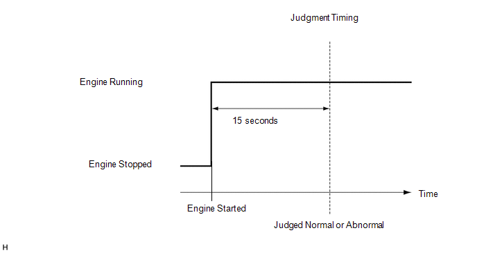
STOP AND START SYSTEM OPERATION CHECK
Click here

WIRING DIAGRAM
CAUTION / NOTICE / HINT
NOTICE:
-
Before replacing the engine stop and start ECU, read the number of starter operations and write it into a new engine stop and start ECU.
Click here

-
After replacing the engine stop and start ECU, perform learning of the external backup boost converter (eco run vehicle converter assembly).
Click here

-
After replacing the engine stop and start ECU or air conditioning amplifier assembly, reset and perform learning of the air conditioning information in the engine stop and start ECU.
Click here

HINT:
-
Using the GTS, read the freeze frame data before troubleshooting. System condition information is recorded as freeze frame data the moment a DTC is stored. This information can be useful when troubleshooting.
Click here

-
For wire harness and connector inspection procedures and precautions, refer to "Click here
 "
"
-
DTCs for the stop and start system are not cleared even if the malfunction has been repaired. After repairing the malfunction, be sure to clear the DTCs.
Click here

PROCEDURE
| 1. | CHECK DTC OUTPUT (SFI SYSTEM) |
(a) Read the DTCs.
Powertrain > Engine > Trouble Codes| Result | Proceed to |
|---|---|
| SFI system DTCs are not output | A |
| SFI system crankshaft position sensor circuit DTC is output | B |
| B |
 | GO TO SFI SYSTEM |
|

| 2. | READ VALUE USING GTS (ENGINE SPEED) |
(a) Start the engine.
Powertrain > Stop and Start > Data List| Tester Display |
|---|
| Engine Speed |
(b) According to the display on the GTS, read the Data List.
OK:
Engine speed signal is input (the speeds displayed on the tachometer and the GTS are almost the same).
| OK |
 | USE SIMULATION METHOD TO CHECK |
|

| 3. | CHECK HARNESS AND CONNECTOR (ENGINE STOP AND START ECU - ECM) |
(a) Disconnect the A67 engine stop and start ECU connector.
(b) Disconnect the A106 ECM connector.
(c) Disconnect the H45 certification ECU (smart key ECU assembly) connector.
(d) Measure the resistance according to the value(s) in the table below.
Standard Resistance:
| Tester Connection | Condition | Specified Condition |
|---|---|---|
| A67-10 (NE) - A106-16 (NEO) | Always | Below 1 Ω |
| A67-10 (NE) - Body ground and other terminals | Always | 10 kΩ or higher |
| A106-16 (NEO) - Body ground and other terminals | Always | 10 kΩ or higher |
| NG |
 | REPAIR OR REPLACE HARNESS OR CONNECTOR |
|

| 4. | CHECK HARNESS AND CONNECTOR (ENGINE STOP AND START ECU - BODY GROUND) |
(a) Disconnect the A67 engine stop and start ECU connector.
(b) Measure the resistance according to the value(s) in the table below.
Standard Resistance:
| Tester Connection | Condition | Specified Condition |
|---|---|---|
| A67-6 (DGND) - Body ground | Always | Below 1 Ω |
| NG |
 | REPAIR OR REPLACE HARNESS OR CONNECTOR |
|

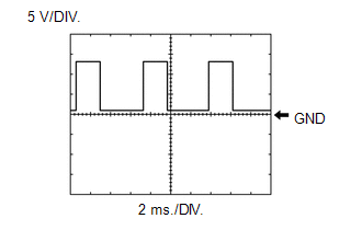
| 5. | CHECK ENGINE STOP AND START ECU (NE SIGNAL INPUT) |
(a) Start the engine and warm it up.
(b) Connect an oscilloscope to the NE and DGND terminals of the engine stop and start ECU connector.

| *a | Component with harness connected (Engine Stop and Start ECU) | - | - |
| (c) Check the signal waveform according to the condition(s) in the table below.
|
|
| A |
 | REPLACE ENGINE STOP AND START ECU |
| C |
 | GO TO SFI SYSTEM |
|

| 6. | CHECK ENGINE STOP AND START ECU (NE TERMINAL VOLTAGE) |
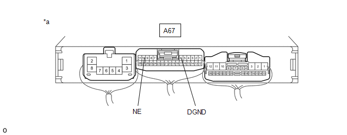
| *a | Component with harness connected (Engine Stop and Start ECU) | - | - |
(a) Disconnect the A106 ECM connector.
(b) Turn the ignition switch to ON.
(c) Measure the voltage according to the value(s) in the table below.
Click here

Standard Voltage:
| Tester Connection | Switch Condition | Specified Condition |
|---|---|---|
| A67-10 (NE) - A67-6 (DGND) | Ignition switch ON | 8 to 14 V |
HINT:
DTCs may be stored during this inspection. Check for DTCs and clear them using the GTS.
| OK |
 | GO TO SFI SYSTEM |
| NG |
 | REPLACE ENGINE STOP AND START ECU |

 Brake Booster Pressure Sensor(running) (P055500,P05552A)
DESCRIPTION The engine stop and start ECU determines changes in the brake booster assembly pressure based on the voltage signal received from the vacuum sensor assembly in the brake booster assembly...
Other information:
Toyota Yaris XP210 (2020-2026) Reapir and Service Manual: Problem Symptoms Table
PROBLEM SYMPTOMS TABLE NOTICE: If the main body ECU (multiplex network body ECU) is replaced, refer to the Registration. Click here HINT: Troubleshooting of the theft deterrent system is based on the premise that the power door lock control system and the wireless door lock control system are operating normally...
Toyota Yaris XP210 (2020-2026) Reapir and Service Manual: Components
COMPONENTS ILLUSTRATION *1 TAIL EXHAUST PIPE ASSEMBLY - - N*m (kgf*cm, ft.*lbf): Specified torque - - ILLUSTRATION *1 NO. 2 AIR FUEL RATIO SENSOR *2 COMPRESSION SPRING *3 EXHAUST PIPE GASKET *4 FRONT EXHAUST PIPE ASSEMBLY *5 CENTER NO...
Categories
- Manuals Home
- Toyota Yaris Owners Manual
- Toyota Yaris Service Manual
- To Set Speed
- Engine Start Function When Key Battery is Dead
- Headlights
- New on site
- Most important about car
Supplemental Restraint System (SRS) Precautions
The front and side supplemental restraint systems (SRS) include different types of air bags. Please verify the different types of air bags which are equipped on your vehicle by locating the “SRS AIRBAG” location indicators. These indicators are visible in the area where the air bags are installed.
The air bags are installed in the following locations:
The steering wheel hub (driver air bag) The front passenger dashboard (front passenger air bag) The outboard sides of the front seatbacks (side air bags) The front and rear window pillars, and the roof edge along both sides (curtain air bags)