
Toyota Yaris: Fuel Pump (for High Pressure) / Components
COMPONENTS
ILLUSTRATION
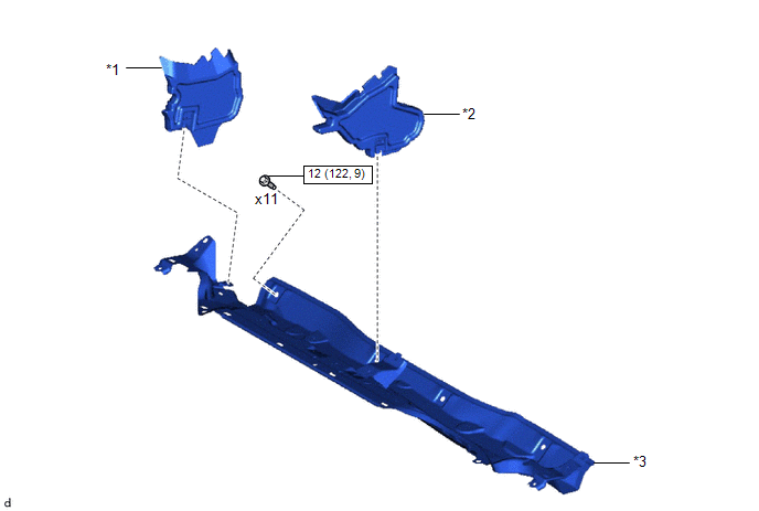
| *1 | WATER GUARD PLATE RH | *2 | NO. 1 FRONT VENTILATOR SEAL |
| *3 | OUTER COWL TOP PANEL SUB-ASSEMBLY | - | - |
 | N*m (kgf*cm, ft.*lbf): Specified torque | - | - |
ILLUSTRATION
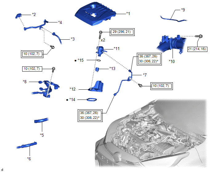
| *1 | NO. 1 ENGINE COVER SUB-ASSEMBLY | *2 | FUEL PIPE CLAMP |
| *3 | NO. 1 FUEL TUBE SUB-ASSEMBLY | *4 | NO. 2 FUEL TUBE SUB-ASSEMBLY |
| *5 | NO. 1 WATER BY-PASS HOSE | *6 | NO. 8 WATER BY-PASS HOSE |
| *7 | NO. 1 FUEL PIPE SUB-ASSEMBLY | *8 | ENGINE WIRE |
| *9 | NO. 1 VACCUM TRANSMITTING HOSE | *10 | INTAKE AIR RESONATOR |
| *11 | FUEL PUMP ASSEMBLY | *12 | FUEL PUMP FLANGE |
| *13 | FUEL PUMP LIFTER ASSEMBLY | *14 | FUEL PUMP SPACER GASKET |
| *15 | O-RING | - | - |
 | Tightening torque for "Major areas involving basic vehicle performance such as moving/turning/stopping": N*m (kgf*cm, ft.*lbf) |
 | N*m (kgf*cm, ft.*lbf): Specified torque |
| * | For use with a union nut wrench | ● | Non-reusable part |

 On-vehicle Inspection
ON-VEHICLE INSPECTION PROCEDURE 1. FUEL PUMP ASSEMBLY OPERATION (a) Check fuel pressure. (1) Connect the GTS to the DLC3. (2) Turn the ignition switch to ON...
Other information:
Toyota Yaris XP210 (2020-2026) Reapir and Service Manual: Installation
INSTALLATION PROCEDURE 1. INSTALL AIR CONDITIONING AMPLIFIER ASSEMBLY (a) Connect the 3 connectors. (b) Engage the guide to install the air conditioning amplifier assembly. (c) Install the 3 screws. (d) Install the front floor carpet assembly with the 2 clips as shown in the illustration...
Toyota Yaris XP210 (2020-2026) Owner's Manual: Brake Pad Wear Indicator
When the disc brake pads become worn, the built-in wear indicators contact the disc plates. This causes a screeching noise to warn that the pads should be replaced. When you hear this noise, consult your Toyota dealer as soon as possible. WARNING Do not drive with worn disc pads Driving with worn disc pads is dangerous...
Categories
- Manuals Home
- Toyota Yaris Owners Manual
- Toyota Yaris Service Manual
- Opening and Closing the Liftgate/Trunk Lid
- Brake System Control Module "A" System Voltage System Voltage Low (C137BA2)
- Removal
- New on site
- Most important about car
Break-In Period
No special break-in is necessary, but a few precautions in the first 600 miles (1,000 km) may add to the performance, economy, and life of the vehicle.
Do not race the engine. Do not maintain one constant speed, either slow or fast, for a long period of time. Do not drive constantly at full-throttle or high engine rpm for extended periods of time. Avoid unnecessary hard stops. Avoid full-throttle starts.