Toyota Yaris: Clutch / Clutch Pedal Switch
Components
COMPONENTS
ILLUSTRATION
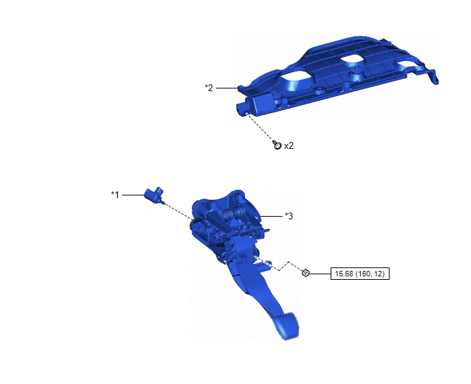
| *1 | CLUTCH START SWITCH ASSEMBLY | *2 | NO. 1 INSTRUMENT PANEL UNDER COVER SUB-ASSEMBLY |
| *3 | CLUTCH PEDAL SUPPORT ASSEMBLY | - | - |
 | N*m (kgf*cm, ft.*lbf): Specified torque | - | - |
On-vehicle Inspection
ON-VEHICLE INSPECTION
PROCEDURE
1. INSPECT CLUTCH START SYSTEM
(a) Check that the engine does not start when the clutch pedal sub-assembly is released.
(b) Check that the engine starts when the clutch pedal sub-assembly is fully depressed.
If necessary, inspect and replace the clutch start switch assembly.
Removal
REMOVAL
PROCEDURE
1. REMOVE NO. 1 INSTRUMENT PANEL UNDER COVER SUB-ASSEMBLY
Click here

2. REMOVE CLUTCH START SWITCH ASSEMBLY
| (a) Disconnect the clutch start switch assembly connector. |
|
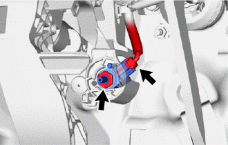
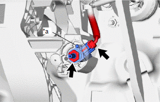
(b) Remove the nut and clutch start switch assembly from the clutch pedal support assembly.
NOTICE:
To prevent damage to the clutch start switch assembly, make sure not to rotate it during removal.
Inspection
INSPECTION
PROCEDURE
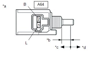
1. INSPECT CLUTCH START SWITCH ASSEMBLY
(a) Check the resistance.
| (1) Measure the resistance according to the value(s) in the table below. Standard Resistance:
If the result is not as specified, replace the clutch start switch assembly. |
|
Installation
INSTALLATION
PROCEDURE
1. INSTALL CLUTCH START SWITCH ASSEMBLY
| (a) Install the clutch start switch assembly to the clutch pedal support assembly with the nut. Torque: 15.68 N·m {160 kgf·cm, 12 ft·lbf} NOTICE:
|
|
(b) Connect the clutch start switch assembly connector.
2. INSTALL NO. 1 INSTRUMENT PANEL UNDER COVER SUB-ASSEMBLY
Click here

3. INSPECT CLUTCH START SYSTEM
Click here

 Installation
INSTALLATION PROCEDURE 1. INSTALL CLUTCH PEDAL PAD (a) Install the clutch pedal pad to the clutch pedal sub-assembly. 2. INSTALL NO. 1 PEDAL SPRING HOOK (a) Install the 2 No...

Other information:
Toyota Yaris XP210 (2020-2026) Reapir and Service Manual: Components
C..
Toyota Yaris XP210 (2020-2026) Reapir and Service Manual: Park/Neutral Switch Circuit Short to Ground (P085011,P085015)
DESCRIPTION The engine stop and start ECU detects a malfunction by comparing the shift position signal with the neutral position switch signal input state. If a malfunction is detected, the engine stop and start ECU blinks the stop and start cancel indicator light, prohibits the stop and start control and stores DTC P085011 or P085015...
Categories
- Manuals Home
- Toyota Yaris Owners Manual
- Toyota Yaris Service Manual
- Battery Monitor Module General Electrical Failure (P058A01)
- Maintenance
- Immobilizer System
- New on site
- Most important about car
Liftgate/Trunk Lid
WARNING
Never allow a person to ride in the luggage compartment/trunk
Allowing a person to ride in the luggage compartment/trunk is dangerous. The person in the luggage compartment/trunk could be seriously injured or killed during sudden braking or a collision.
Do not drive with the liftgate/trunk lid open