Toyota Yaris: Dynamic Radar Cruise Control System / Distance Control Switch Circuit
DESCRIPTION
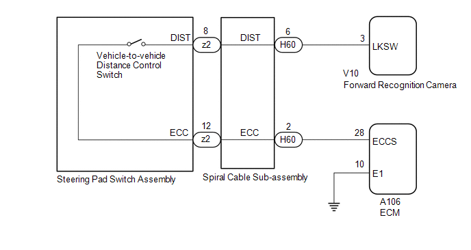
The vehicle-to-vehicle distance control switch is used to set the distance for vehicle-to-vehicle distance control mode. The vehicle-to-vehicle distance control switch is installed in the steering pad switch assembly. The vehicle-to-vehicle distance set value can be changed by operating the vehicle-to-vehicle distance control switch while the dynamic radar cruise control system is controlling vehicle speed in vehicle-to-vehicle distance control mode.
WIRING DIAGRAM
CAUTION / NOTICE / HINT
NOTICE:
- Before replacing the ECM, refer to Service Bulletin.
-
The vehicle is equipped with a Supplemental Restraint System (SRS) which includes components such as airbags. Before servicing (including removal or installation of parts), be sure to read the precaution for Supplemental Restraint System.
Click here

- When replacing the forward recognition camera, always replace it with a new one. If a forward recognition camera which was installed to another vehicle is used, the information stored in the forward recognition camera will not match the information from the vehicle and a DTC may be stored.
-
When the forward recognition camera is replaced with a new one or the windshield glass is replaced or removed/installed, make sure to read Before Starting Adjustment, then perform optical axis alignment for the forward recognition camera and clear the vehicle control history for each system.
HINT:
Forward recognition camera axis alignment can be performed by using either One Time Recognition, Sequential Recognition or Driving Adjustment.
One Time Recognition: Click here

Sequential Recognition: Click here

Driving Adjustment: Click here

PROCEDURE
| 1. | READ VALUE USING GTS (VEHICLE-TO-VEHICLE DISTANCE CONTROL SWITCH) |
(a) Read the Data List according to the display on the GTS.
Powertrain > Radar Cruise2 > Data List| Tester Display | Measurement Item | Range | Normal Condition | Diagnostic Note |
|---|---|---|---|---|
| Vehicle-to-vehicle Distance Control Switch | Vehicle-to-vehicle distance control switch signal | ON or OFF | ON: Vehicle-to-vehicle distance control switch pushed OFF: Vehicle-to-vehicle distance control switch not pushed | - |
| Tester Display |
|---|
| Vehicle-to-vehicle Distance Control Switch |
OK:
The value of the Data List item changes according to the operation of the vehicle-to-vehicle distance control switch.
| OK |
 | PROCEED TO NEXT SUSPECTED AREA SHOWN IN PROBLEM SYMPTOMS TABLE |
|

| 2. | INSPECT STEERING PAD SWITCH ASSEMBLY |
Click here

| NG |
 | REPLACE STEERING PAD SWITCH ASSEMBLY |
|

| 3. | INSPECT SPIRAL CABLE SUB-ASSEMBLY |
Click here

| NG |
 | REPLACE SPIRAL CABLE SUB-ASSEMBLY |
|

| 4. | CHECK HARNESS AND CONNECTOR (SPIRAL CABLE SUB-ASSEMBLY - FORWARD RECOGNITION CAMERA, ECM AND BODY GROUND) |
(a) Disconnect the H60 spiral cable sub-assembly connector.
(b) Disconnect the V10 forward recognition camera connector.
(c) Disconnect the A106 ECM connector.
(d) Measure the resistance according to the value(s) in the table below.
Standard Resistance:
| Tester Connection | Condition | Specified Condition |
|---|---|---|
| H60-6 (DIST) - V10-3 (LKSW) | Always | Below 1 Ω |
| H60-2 (ECC) - A106-28 (ECCS) | Always | Below 1 Ω |
| H60-6 (DIST) or V10-3 (LKSW) - Body ground | Always | 10 kΩ or higher |
| H60-2 (ECC) or A106-28 (ECCS) - Body ground | Always | 10 kΩ or higher |
(e) Connect the A106 ECM connector.
(f) Connect the V10 forward recognition camera connector.
(g) Connect the H60 spiral cable sub-assembly connector.
| NG |
 | REPAIR OR REPLACE HARNESS OR CONNECTOR |
|

| 5. | CHECK HARNESS AND CONNECTOR (ECM - BODY GROUND) |
(a) Disconnect the A106 ECM connector.
(b) Measure the resistance according to the value(s) in the table below.
Standard Resistance:
| Tester Connection | Condition | Specified Condition |
|---|---|---|
| A106-10 (E1) - Body ground | Always | Below 1 Ω |
(c) Connect the A106 ECM connector.
| NG |
 | REPAIR OR REPLACE HARNESS OR CONNECTOR |
|

| 6. | CHECK ECM (ECM TERMINALS) |
(a) Disconnect the A106 ECM connector.
(b) Measure the resistance according to the value(s) in the table below.
Standard Resistance:
| Tester Connection | Condition | Specified Condition |
|---|---|---|
| A106-28 (ECCS) - A106-10 (E1) | Always | Below 1 Ω |
(c) Connect the A106 ECM connector.
| OK |
 | REPLACE FORWARD RECOGNITION CAMERA |
| NG |
 | REPLACE ECM |
 Steering Pad Switch Circuit
DESCRIPTION
The steering pad switch assembly outputs the dynamic cruise control on/off signal and various control signals to the ECM.
The ECM controls the dynamic cruise control system according to the signals received from the steering pad switch assembly...
 Cruise Main Indicator Light Circuit
DESCRIPTION When the dynamic radar cruise control system is turned on using the cruise control main switch, the cruise control indicator (vehicle-to-vehicle distance control mode) illuminates...
Other information:
Toyota Yaris XP210 (2020-2026) Reapir and Service Manual: Installation
INSTALLATION PROCEDURE 1. INSTALL AIR CONDITIONER PRESSURE SENSOR (a) Remove the vinyl tape from the No. 2 air conditioner tube and accessory assembly. (b) Sufficiently apply compressor oil to a new air conditioner pressure sensor and the fitting surface of the air conditioner pressure sensor...
Toyota Yaris XP210 (2020-2026) Reapir and Service Manual: How To Proceed With Troubleshooting
CAUTION / NOTICE / HINT HINT: Use the following procedure to troubleshoot the seat belt warning system. *: Use the GTS. PROCEDURE 1. VEHICLE BROUGHT TO WORKSHOP NEXT 2. CUSTOMER PROBLEM ANALYSIS (a) Interview the customer to confirm the trouble...
Categories
- Manuals Home
- Toyota Yaris Owners Manual
- Toyota Yaris Service Manual
- Brake System Control Module "A" System Voltage System Voltage Low (C137BA2)
- Engine & Hybrid System
- Power Integration No.1 System Missing Message (B235287,B235587,B235787-B235987)
- New on site
- Most important about car
Keys

To use the auxiliary key, press the knob and pull out the auxiliary key from the smart key.
