Toyota Yaris: Back Door / Adjustment
ADJUSTMENT
CAUTION / NOTICE / HINT
HINT:
- Centering bolts are used to install the door hinges to the door. The door cannot be adjusted with the centering bolts installed. Substitute the centering bolts with standard bolts (with washers) when making adjustments.
-
The specified torque for standard bolts is shown in the standard bolt chart.
Click here
.gif)
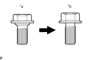
| *a | Centering Bolt |
| *b | Standard Bolt |
PROCEDURE
1. INSPECT BACK DOOR PANEL SUB-ASSEMBLY
(a) Check that the clearance measurements of areas "A" to "K" are within the standard ranges.
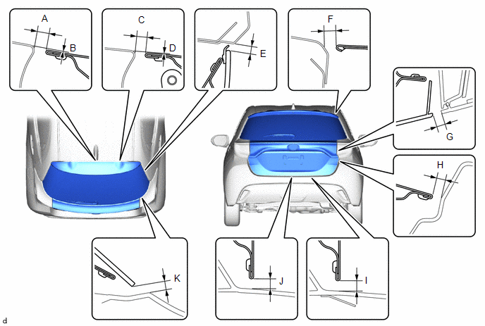
Standard Clearance:
| Area | Measurement | Area | Measurement |
|---|---|---|---|
| A | 6.0 to 9.0 mm (0.236 to 0.354 in.) | B | -0.5 to 2.5 mm (-0.0197 to 0.098 in.) |
| C | 6.0 to 9.0 mm (0.236 to 0.354 in.) | D | -0.5 to 2.5 mm (-0.0197 to 0.098 in.) |
| E | 3.0 to 8.0 mm (0.118 to 0.315 in.) | F | 4.8 to 7.8 mm (0.189 to 0.307 in.) |
| G | 4.9 to 8.9 mm (0.193 to 0.350 in.) | H | 3.1 to 8.1 mm (0.122 to 0.319 in.) |
| I | 3.5 to 8.5 mm (0.138 to 0.335 in.) | J | 3.5 to 8.5 mm (0.138 to 0.335 in.) |
| K | 4.2 to 9.2 mm (0.165 to 0.362 in.) | - | - |
2. REMOVE DECK BOARD ASSEMBLY
Click here
3. REMOVE DECK TRIM REAR COVER
Click here
4. ADJUST BACK DOOR PANEL SUB-ASSEMBLY
| (a) Loosen the 4 hinge bolts on the back door and adjust the back door position. |
|
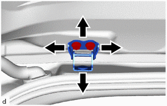
(b) Tighten the 4 hinge bolts on the back door after adjustment.
Torque:
19 N·m {194 kgf·cm, 14 ft·lbf}
HINT:
Use the same procedure for the RH side and LH side.
| (c) Using a T40 "TORX" socket wrench, slightly loosen the 2 striker mounting screws. |
|
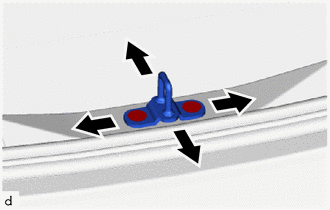
(d) Using a brass bar and a hammer, hit the striker to adjust its position.
(e) Using a T40 "TORX" socket wrench, tighten the 2 striker mounting screws after adjustment.
Torque:
23 N·m {235 kgf·cm, 17 ft·lbf}
5. INSTALL DECK TRIM REAR COVER
Click here
6. INSTALL DECK BOARD ASSEMBLY
Click here
 Disassembly
DISASSEMBLY CAUTION / NOTICE / HINT PROCEDURE 1. REMOVE BACK DOOR TRIM BOARD (a) Remove the 11 clips and back door trim board.
2. REMOVE BACK DOOR TRIM COVER (a) Disengage the clips to remove the back door trim cover...
 Reassembly
REASSEMBLY PROCEDURE 1. INSTALL BACK DOOR DUST PROOF SEAL (a) Engage the claw to install 3 new back door dust proof seals.
2. INSTALL NO...
Other information:
Toyota Yaris XP210 (2020-2026) Reapir and Service Manual: Reassembly
REASSEMBLY PROCEDURE 1. INSTALL FRONT BUMPER LOWER ABSORBER (a) Install the 4 grommets. (b) Engage the claws to install the front bumper lower absorber. (c) Install the clip and 5 screws. 2. INSTALL NO. 1 ENGINE UNDER COVER ASSEMBLY Click here 3...
Toyota Yaris XP210 (2020-2026) Reapir and Service Manual: Wiper Module Missing Message (B235787)
DESCRIPTION The main body ECU (multiplex network body ECU) and windshield wiper relay assembly communicate via CXPI communication. The main body ECU (multiplex network body ECU) stores this DTC if communication becomes abnormal. DTC No. Detection Item DTC Detection Condition Trouble Area Memory DTC Output from B235787 Wiper Module Missing Message Auxiliary battery voltage is 9...
Categories
- Manuals Home
- Toyota Yaris Owners Manual
- Toyota Yaris Service Manual
- Opening and Closing the Liftgate/Trunk Lid
- Fuse Panel Description
- How to connect USB port/Auxiliary jack
- New on site
- Most important about car
Turning the Engine Off
Stop the vehicle completely. Manual transaxle: Shift into neutral and set the parking brake.Automatic transaxle: Shift the selector lever to the P position and set the parking brake.
Press the push button start to turn off the engine. The ignition position is off.