Toyota Yaris: Active Torque Split Awd System / 4WD/AWD Front/Rear Range Actuator Control Circuit Performance Circuit Voltage Out of Range (C05F51C)
DESCRIPTION
When a malfunction has occurred in the AWD coupling solenoid system, the AWD ECU assembly stores DTC C05F51C.
| DTC No. | Detection Item | DTC Detection Condition | Trouble Area | Warning Indicate | Memory |
|---|---|---|---|---|---|
| C05F51C | 4WD/AWD Front/Rear Range Actuator Control Circuit Performance Circuit Voltage Out of Range |
|
| Displayed | Yes |
| Vehicle Condition | |||
|---|---|---|---|
| Pattern 1 | Pattern 2 | ||
| Diagnosis Condition | IG1 terminal voltage is 9.5 V or more and current requested by AWD linear solenoid is 0 A | ○ | - |
| IG1 terminal voltage is 9.5 V or more and current requested by AWD linear solenoid is 0.8 A | - | ○ | |
| Malfunction Status | Short circuit | ○ | - |
| Open circuit | - | ○ | |
| Detection Time | 1 second or more | 1 second or more | |
| Number of Trips | 1 trip | 1 trip | |
HINT:
DTC will be output when conditions for either of the patterns in the table above are met.
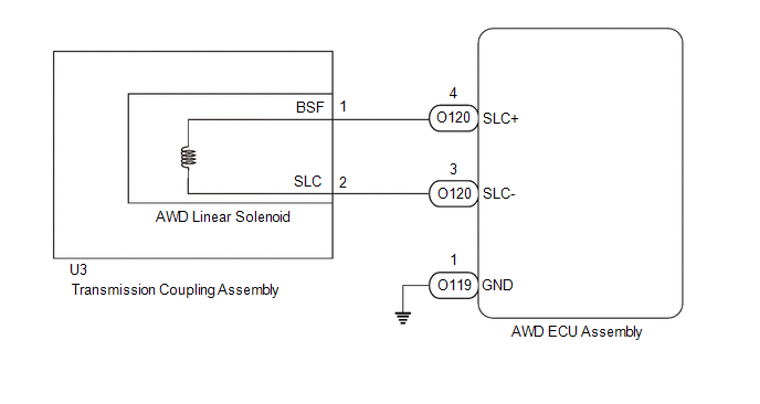
WIRING DIAGRAM
CAUTION / NOTICE / HINT
NOTICE:
-
When the AWD ECU assembly is replaced, before removing the AWD ECU assembly, it is necessary to perform ECU Data Save to save the original AWD ECU assembly information.
Click here

-
After performing repairs, clear the DTCs and check that the DTCs are not output again.
Click here

PROCEDURE
| 1. | CHECK HARNESS AND CONNECTOR (AWD ECU ASSEMBLY - AWD LINEAR SOLENOID (TRANSMISSION COUPLING ASSEMBLY)) |
(a) Turn the ignition switch off.
(b) Disconnect the O120 AWD ECU assembly connector.
(c) Measure the resistance according to the value(s) in the table below.
Standard Resistance:
| Tester Connection | Condition | Specified Condition |
|---|---|---|
| O120-4 (SLC+) - O120-3 (SLC-) | 20°C (68°F) | 2.2 to 2.6 Ω |
| O120-4 (SLC+) - Body ground | Always | 10 kΩ or higher |
| NG |
 | GO TO STEP 3 |
|

| 2. | CHECK HARNESS AND CONNECTOR (AWD ECU ASSEMBLY - AWD LINEAR SOLENOID (TRANSMISSION COUPLING ASSEMBLY)) |
(a) Turn the ignition switch off.
(b) Disconnect the O120 AWD ECU assembly connector.
(c) Measure the voltage according to the value(s) in the table below.
Standard Voltage:
| Tester Connection | Condition | Specified Condition |
|---|---|---|
| O120-3 (SLC-) - Body ground | Always | Below 1 V |
| OK |
 | REPLACE AWD ECU ASSEMBLY |
|

| 3. | CHECK HARNESS AND CONNECTOR (AWD ECU ASSEMBLY - AWD LINEAR SOLENOID (TRANSMISSION COUPLING ASSEMBLY)) |
(a) Turn the ignition switch off.
(b) Disconnect the O119 and O120 AWD ECU assembly connector.
(c) Disconnect the U3 AWD linear solenoid (transmission coupling assembly) connector.
(d) Measure the resistance according to the value(s) in the table below.
Standard Resistance:
| Tester Connection | Condition | Specified Condition |
|---|---|---|
| O120-4 (SLC+) - U3-1 (BSF) | Always | Below 1 Ω |
| O120-3 (SLC-) - U3-2 (SLC) | Always | Below 1 Ω |
| O119-1 (GND) - Body ground | Always | Below 1 Ω |
| O120-4 (SLC+) or U3-1 (BSF) - Body ground | Always | 10 kΩ or higher |
| O120-3 (SLC-) or U3-2 (SLC) - Body ground | Always | 10 kΩ or higher |
| O120-4 (SLC+) or U3-1 (BSF) - O120-3 (SLC-) or U3-2 (SLC) | Always | 10 kΩ or higher |
| O120-4 (SLC+) - O119-1 (GND) | Always | 10 kΩ or higher |
| O120-3 (SLC-) - O119-1 (GND) | Always | 10 kΩ or higher |
| NG |
 | REPAIR OR REPLACE HARNESS OR CONNECTOR |
|

| 4. | CHECK HARNESS AND CONNECTOR (AWD ECU ASSEMBLY - AWD LINEAR SOLENOID (TRANSMISSION COUPLING ASSEMBLY)) |
(a) Turn the ignition switch off.
(b) Disconnect the O120 AWD ECU assembly connector.
(c) Disconnect the U3 AWD linear solenoid (transmission coupling assembly) connector.
(d) Measure the voltage according to the value(s) in the table below.
Standard Voltage:
| Tester Connection | Condition | Specified Condition |
|---|---|---|
| O120-3 (SLC-) or U3-2 (SLC) - Body ground | Always | Below 1 V |
| NG |
 | REPAIR OR REPLACE HARNESS OR CONNECTOR |
|

| 5. | INSPECT AWD LINEAR SOLENOID (TRANSMISSION COUPLING ASSEMBLY) |
(a) Turn the ignition switch off.
(b) Disconnect the U3 AWD linear solenoid (transmission coupling assembly) connector.
(c) Measure the resistance according to the value(s) in the table below.
Standard Resistance:
| Standard Resistance | Condition | Specified Condition |
|---|---|---|
| U3-1 (BSF) - U3-2 (SLC) | 20°C (68°F) | 2.2 to 2.6 Ω |
| OK |
 | USE SIMULATION METHOD TO CHECK |
| NG |
 | REPLACE TRANSMISSION COUPLING ASSEMBLY |
 Vehicle Control History
VEHICLE CONTROL HISTORY NOTICE: When checking the vehicle control history, first record the output codes and after clearing the history, check the output history again...
 4WD/AWD Range Actuator Temperature Sensor Circuit Range/Performance Circuit Voltage Out of Range (C11411C)
DESCRIPTION When a malfunction has occurred in the AWD coupling solenoid system, the AWD ECU assembly stores DTC C11411C. DTC No. Detection Item DTC Detection Condition Trouble Area Warning Indicate Memory C11411C 4WD/AWD Range Actuator Temperature Sensor Circuit Range/Performance Circuit Voltage Out of Range
Even though it can be inferred from the driving conditions that the coupling is generating a significant amount of heat, the temperature sensor value is approximately -10°C (14°F) for 1 second or more, and this continues despite the ignition switch being turned off and then ON again 2 times
Even though the engine coolant temperature received from the ECM is less than 35°C (95°F), the temperature sensor value is fixed at 155°C (311°F) (short circuit condition), and this continues despite the ignition switch being turned off and then ON again 2 times
The temperature sensor power source voltage is 0...
Other information:
Toyota Yaris XP210 (2020-2026) Reapir and Service Manual: Disassembly
DISASSEMBLY CAUTION / NOTICE / HINT The necessary procedures (adjustment, calibration, initialization, or registration) that must be performed after parts are removed and installed, or replaced during cylinder head removal/installation are shown below...
Toyota Yaris XP210 (2020-2026) Owner's Manual: Front Seat
Seat Operation Seat SlideTo move a seat forward or backward, raise the lever and slide the seat to the desired position and release the lever. Make sure the lever returns to its original position and the seat is locked in place by attempting to push it forward and backward...
Categories
- Manuals Home
- Toyota Yaris Owners Manual
- Toyota Yaris Service Manual
- How to connect USB port/Auxiliary jack
- Adjustment
- Diagnostic Trouble Code Chart
- New on site
- Most important about car
Fuel-Filler Lid and Cap
WARNING
When removing the fuel-filler cap, loosen the cap slightly and wait for any hissing to stop, then remove it
Fuel spray is dangerous. Fuel can burn skin and eyes and cause illness if ingested. Fuel spray is released when there is pressure in the fuel tank and the fuel-filler cap is removed too quickly.