Toyota Yaris: Power Integration System / Terminals Of Ecu
TERMINALS OF ECU
NOTICE:
-
After the ignition switch is turned off, there may be a waiting time before disconnecting the negative (-) auxiliary battery terminal.
Click here

-
When disconnecting and reconnecting the auxiliary battery.
Click here

CHECK POWER DISTRIBUTION BOX ASSEMBLY AND MAIN BODY ECU (MULTIPLEX NETWORK BODY ECU)
(a) Remove the main body ECU (multiplex network body ECU) from the power distribution box assembly.
Click here

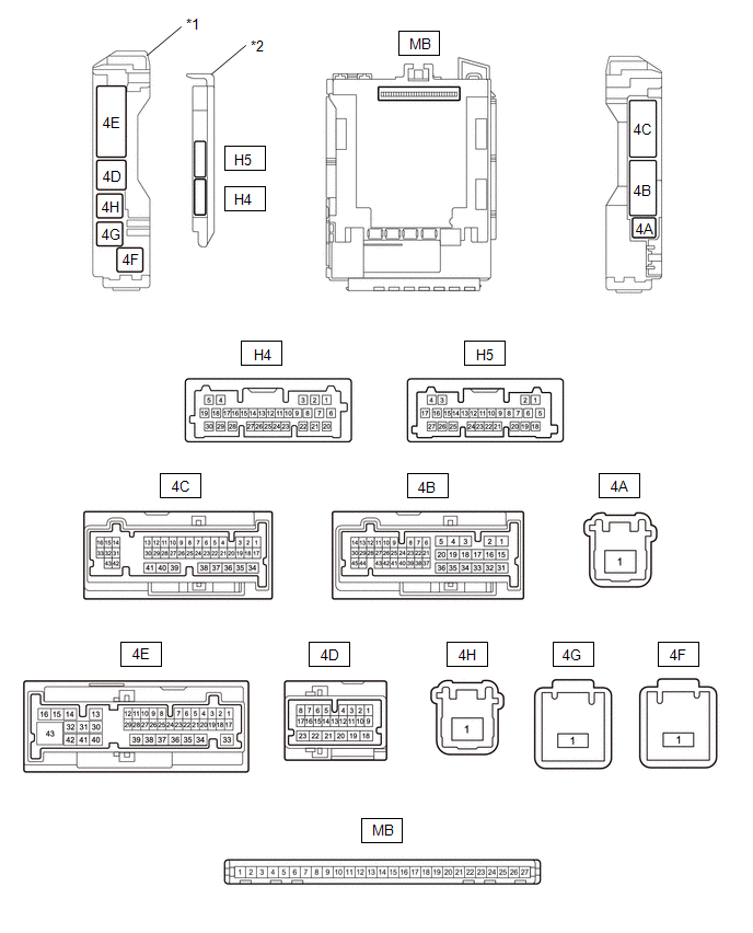
| *1 | Power Distribution Box Assembly | *2 | Main Body ECU (Multiplex Network Body ECU) |
(b) Reconnect the power distribution box assembly connectors.
Click here

(c) Measure the voltage and resistance according to the value(s) in the table below.
| Terminal No. (Symbol) | Terminal Description | Condition | Specified Condition |
|---|---|---|---|
| MB-13 (GND1) - Body ground | Ground | Always | Below 1 Ω |
| MB-26 (BECU) - Body ground | Auxiliary battery power supply | Ignition switch off | 11 to 14 V |
| MB-27 (IGR) - Body ground | IG power supply | Ignition switch off | Below 1 V |
| Ignition switch ON | 11 to 14 V |
(d) Install the main body ECU (multiplex network body ECU) to power distribution box assembly.
Click here

(e) Measure the voltage and check for pulses according to the value(s) in the table below.
| Terminal No. (Symbol) | Terminal Description | Condition | Specified Condition |
|---|---|---|---|
| 4D-5 - Body ground | CXPI communication line | Ignition switch ON | Pulse generation |
| 4E-43 - Body ground | Rear window defogger signal (output) | rear window defogger switch off | Below 1.5 V |
| rear window defogger switch on | 8 to 14 V | ||
| 4B-2 - Body ground | Mirror heater drive voltage (output) | Ignition switch ON, rear defogger switch off | Below 1.5 V |
| Ignition switch ON, rear defogger switch on | 8 to 14 V | ||
| 4C-10 - Body ground | Power retract mirror motor drive voltage (output) | Outer rear view mirror assembly moves to the retracted position | Below 1.5 V |
| Outer rear view mirror assembly not move | 8 to 14 V | ||
| 4C-21 - Body ground | Power retract mirror motor drive voltage (output) | Outer rear view mirror assembly moves to the return position | Below 1.5 V |
| Outer rear view mirror assembly not move | 8 to 14 V |
CHECK SEMICONDUCTOR POWER INTEGRATION ECU

| *a | Component without harness connected (Semiconductor power integration ECU) | - | - |
(a) Disconnect the cable from the negative (-) auxiliary battery terminal.
(b) Disconnect the A85 and A86 semiconductor power integration ECU connectors.
(c) Connect the cable to the negative (-) auxiliary battery terminal.
(d) Measure the resistance and voltage according to the value(s) in the table below.
| Terminal No. (Symbol) | Terminal Description | Condition | Specified Condition |
|---|---|---|---|
| A85-1 (+B) - Body ground | Auxiliary battery power supply | Ignition switch off | 8 to 14 V |
| A86-5 (-S) - Body ground | Headlight ECU sub-assembly operation signal input | Ignition switch off | 6 V or higher |
| Ignition switch ON | Below 1.7 V | ||
| A86-16 (GND2) - Body ground | Ground | Always | Below 1 Ω |
| A86-20 (IG) - Body ground | IG power supply | Ignition switch off | Below 1.5 V |
| Ignition switch ON | 8 to 14 V | ||
| A86-24 (-S) - Body ground | Headlight ECU sub-assembly operation signal input | Ignition switch off | 6 V or higher |
| Ignition switch ON | Below 1.7 V | ||
| A86-26 (GND1) - Body ground | Ground | Always | Below 1 Ω |
(e) Reconnect the A85 and A86 semiconductor power integration ECU connectors.
(f) Measure the voltage and check for pulses according to the value(s) in the table below.
| Terminal No. (Symbol) | Terminal Description | Condition | Specified Condition |
|---|---|---|---|
| A86-8 (CXPI) - Body ground | CXPI communication line | Ignition switch ON | Pulse generation |
| A86-1 (L) - Body ground | Headlight ECU sub-assembly LH power supply | Ignition switch off | Below 3.0 V |
| Ignition switch ON | 8 V or higher | ||
| A86-2 (L)- Body ground | Headlight ECU sub-assembly RH power supply | Ignition switch off | Below 3.0 V |
| Ignition switch ON | 8 V or higher | ||
| A86-17 (L) - Body ground | Front fog light output | Front fog light not illuminated | Below 3.0 V |
| Front fog light illuminated | 8 V or higher | ||
| A86-18 (L) - Body ground | Front fog light output | Front fog light not illuminated | Below 3.0 V |
| Front fog light illuminated | 8 V or higher |
 Problem Symptoms Table
PROBLEM SYMPTOMS TABLE HINT: Use the table below to help determine the cause of the problem symptom. If multiple suspected areas are listed, the potential causes of the symptoms are listed in order of probability in the "Suspected Area" column of the table...
 Dtc Check / Clear
DTC CHECK / CLEAR CHECK DTC (a) Check semiconductor power integration ECU (1) Check for DTCs. Body Electrical > Power Integration No.1 > Trouble Codes (b) Check power distribution box assembly (1) Check for DTCs...
Other information:
Toyota Yaris XP210 (2020-2026) Reapir and Service Manual: Tire Repair Seal
DisposalDISPOSAL PROCEDURE 1. DISPOSE OF TIRE REPAIR SEAL HINT: Confirm the expiration date on the side of the repair seal bottle. (a) Dispose of the retrieved seal by consigning disposal to a waste disposal firm. NOTICE: The valve and valve core cannot be reused...
Toyota Yaris XP210 (2020-2026) Reapir and Service Manual: Driver Side Power Window does not Operate with Power Window Master Switch
DESCRIPTION When the ignition switch is ON, the power window regulator motor assembly (for driver door) is operated by the multiplex network master switch assembly. The power window regulator motor assembly (for driver door) has motor, regulator and ECU functions...
Categories
- Manuals Home
- Toyota Yaris Owners Manual
- Toyota Yaris Service Manual
- Brake System Control Module "A" System Voltage System Voltage Low (C137BA2)
- How to use USB mode
- Headlights
- New on site
- Most important about car
Break-In Period
No special break-in is necessary, but a few precautions in the first 600 miles (1,000 km) may add to the performance, economy, and life of the vehicle.
Do not race the engine. Do not maintain one constant speed, either slow or fast, for a long period of time. Do not drive constantly at full-throttle or high engine rpm for extended periods of time. Avoid unnecessary hard stops. Avoid full-throttle starts.