
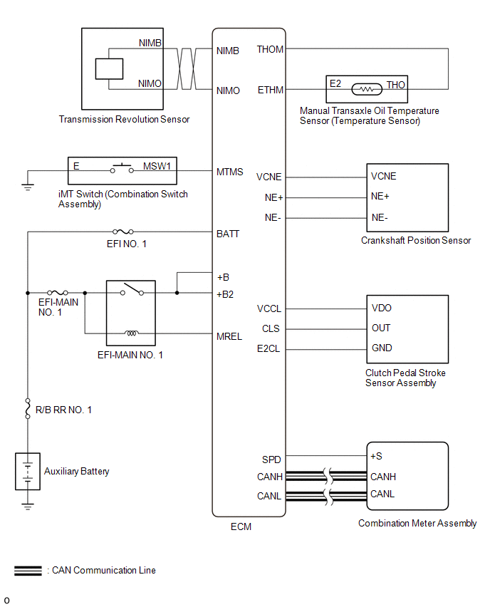
Toyota Yaris: Manual Transaxle System / System Diagram
SYSTEM DIAGRAM
 Parts Location
P..
 How To Proceed With Troubleshooting
CAUTION / NOTICE / HINT HINT:
The ECM of this system is connected to the CAN communication system. Therefore, before starting troubleshooting, be sure to check that there are no malfunctions in the CAN communication system...
Other information:
Toyota Yaris XP210 (2020-2026) Reapir and Service Manual: Lost Communication With ECM/PCM "A" Missing Message (U010087,U010187,U012687,U012987,U014087,U015587)
DESCRIPTION When a malfunction is detected between various ECUs and sensors, these DTCs are stored. DTC No. Detection Item DTC Detection Condition Trouble Area U010087 Lost Communication With ECM/PCM "A" Missing Message When the ignition switch is ON for 3 seconds or more, and the vehicle is being driven at a speed of 5 km/h (3mph) or more, a communication malfunction between the forward recognition camera and the ECM continues for 2 seconds or more...
Toyota Yaris XP210 (2020-2026) Reapir and Service Manual: Inspection
INSPECTION PROCEDURE 1. INSPECT FUEL PUMP (a) Measure the resistance according to the value(s) in the table below. Standard Resistance: Tester Connection Specified Condition U - V 0.05 to 3.0 Ω V - W 0.05 to 3.0 Ω U - W 0...
Categories
- Manuals Home
- Toyota Yaris Owners Manual
- Toyota Yaris Service Manual
- To Set Speed
- Headlights
- Removal
- New on site
- Most important about car
Key Suspend Function
If a key is left in the vehicle, the functions of the key left in the vehicle are temporarily suspended to prevent theft of the vehicle.
To restore the functions, press the unlock button on the functions-suspended key in the vehicle.

Copyright © 2026 www.toyaris4.com