Toyota Yaris: Inner Rear View Mirror / System Diagram
SYSTEM DIAGRAM
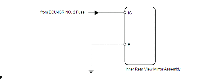
 Components
COMPONENTS ILLUSTRATION
*A w/ Pre-collision System *B w/o Pre-collision System *1 INNER REAR VIEW MIRROR ASSEMBLY *2 INNER REAR VIEW MIRROR STAY HOLDER COVER *3 NO...
 Problem Symptoms Table
PROBLEM SYMPTOMS TABLE HINT: Use the table below to help determine the cause of problem symptoms. If multiple suspected areas are listed, the potential causes of the symptoms are listed in order of probability in the "Suspected Area" column of the table...
Other information:
Toyota Yaris XP210 (2020-2026) Reapir and Service Manual: Front Door Left Speaker Circuit Actuator Stuck (B1AAE71)
DESCRIPTION This DTC is output when a malfunction occurs in the left side front speaker system. DTC No. Detection Item DTC Detection Condition Trouble Area B1AAE71 Front Door Left Speaker Circuit Actuator Stuck When starting the system from IG OFF → ACC ON, the stereo component equalizer assembly detects a malfunction in the left side front speaker system* Harness or connector Front No...
Toyota Yaris XP210 (2020-2026) Reapir and Service Manual: Problem Symptoms Table
PROBLEM SYMPTOMS TABLE NOTICE: Use the table below to help determine the cause of problem symptoms. If multiple suspected areas are listed, the potential causes of the symptoms are listed in order of probability in the "Suspected Area" column of the table...
Categories
- Manuals Home
- Toyota Yaris Owners Manual
- Toyota Yaris Service Manual
- Removal
- Adjustment
- Opening and Closing the Liftgate/Trunk Lid
- New on site
- Most important about car
Supplemental Restraint System (SRS) Precautions
The front and side supplemental restraint systems (SRS) include different types of air bags. Please verify the different types of air bags which are equipped on your vehicle by locating the “SRS AIRBAG” location indicators. These indicators are visible in the area where the air bags are installed.
The air bags are installed in the following locations:
The steering wheel hub (driver air bag) The front passenger dashboard (front passenger air bag) The outboard sides of the front seatbacks (side air bags) The front and rear window pillars, and the roof edge along both sides (curtain air bags)
Copyright © 2026 www.toyaris4.com