Toyota Yaris: Power Window Control System / System Diagram
SYSTEM DIAGRAM
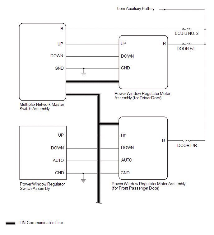
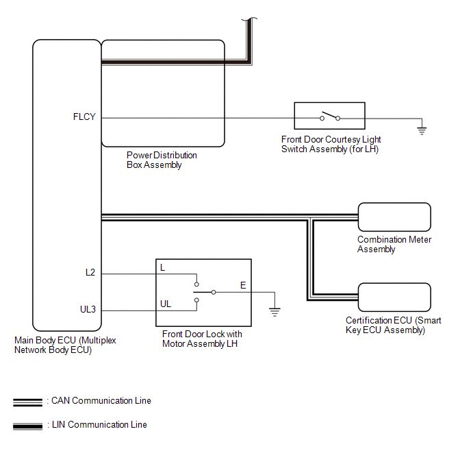 Communication Table
 | Transmitting ECU | Receiving ECU | Signal | Communication Method |
|---|---|---|---|
| Multiplex Network Master Switch Assembly | Power Window Regulator Motor Assembly (for Driver Door) | Power window auto up and down signal | LIN |
| Power window remote up and down signal | LIN | |
| Main Body ECU (Multiplex Network Body ECU) |
| Power window operation permission signal | LIN |
| Certification ECU (Smart Key ECU Assembly) | Main Body ECU (Multiplex Network Body ECU) | Wireless power window operation signal | CAN |
| Main Body ECU (Multiplex Network Body ECU) | Combination Meter Assembly | Window open warning request signal | CAN |
 Parts Location
PARTS LOCATION ILLUSTRATION
*1 COMBINATION METER ASSEMBLY *2 MAIN BODY ECU (MULTIPLEX NETWORK BODY ECU) *3 POWER DISTRIBUTION BOX ASSEMBLY - DOOR F/R FUSE - DOOR F/L FUSE - DOOR R/R FUSE - DOOR R/L FUSE - ECU-B NO...
 System Description
SYSTEM DESCRIPTION POWER WINDOW CONTROL SYSTEM DESCRIPTION (a) The power window control system controls the power window operation using the power window regulator motor assemblies...
Other information:
Toyota Yaris XP210 (2020-2026) Reapir and Service Manual: Data List / Active Test
DATA LIST / ACTIVE TEST DATA LIST HINT: Using the GTS to read the Data List allows the values or states of switches, sensors, actuators and other items to be read without removing any parts. This non-intrusive inspection can be very useful because intermittent conditions or signals may be discovered before parts or wiring is disturbed...
Toyota Yaris XP210 (2020-2026) Reapir and Service Manual: Components
COMPONENTS ILLUSTRATION *1 FAN AND GENERATOR V BELT *2 ENGINE WIRE *3 NO. 2 AIR HOSE *4 ENGINE UNDER COVER RH *5 NO. 1 AIR TUBE *6 COMPRESSOR ASSEMBLY WITH PULLEY *7 NO. 1 ENGINE UNDER COVER ASSEMBLY - - N*m (kgf*cm, ft...
Categories
- Manuals Home
- Toyota Yaris Owners Manual
- Toyota Yaris Service Manual
- G16e-gts (engine Mechanical)
- Opening and Closing the Liftgate/Trunk Lid
- To Set Speed
- New on site
- Most important about car
Supplemental Restraint System (SRS) Precautions
The front and side supplemental restraint systems (SRS) include different types of air bags. Please verify the different types of air bags which are equipped on your vehicle by locating the “SRS AIRBAG” location indicators. These indicators are visible in the area where the air bags are installed.
The air bags are installed in the following locations:
The steering wheel hub (driver air bag) The front passenger dashboard (front passenger air bag) The outboard sides of the front seatbacks (side air bags) The front and rear window pillars, and the roof edge along both sides (curtain air bags)