Toyota Yaris: Sfi System / System Diagram
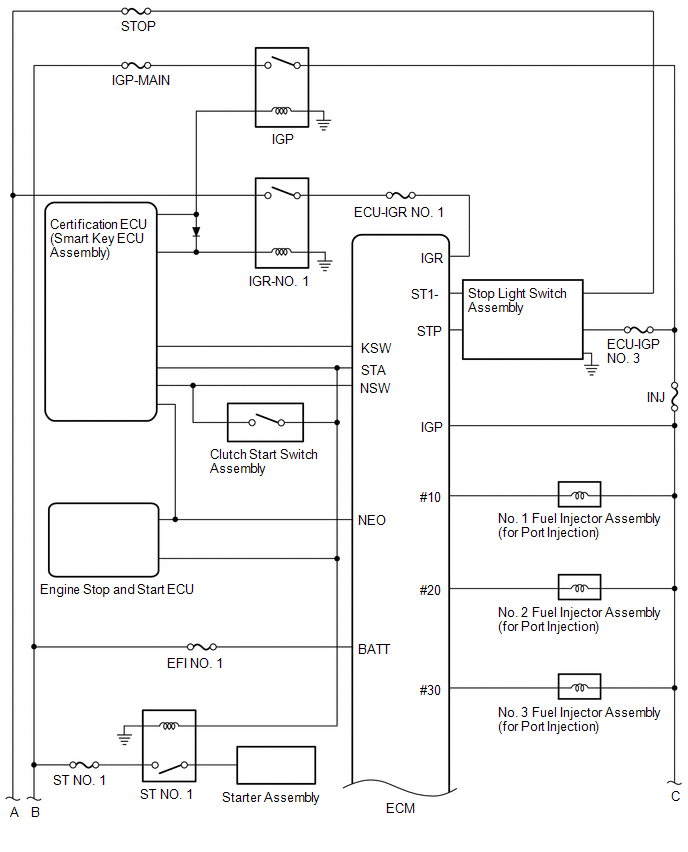
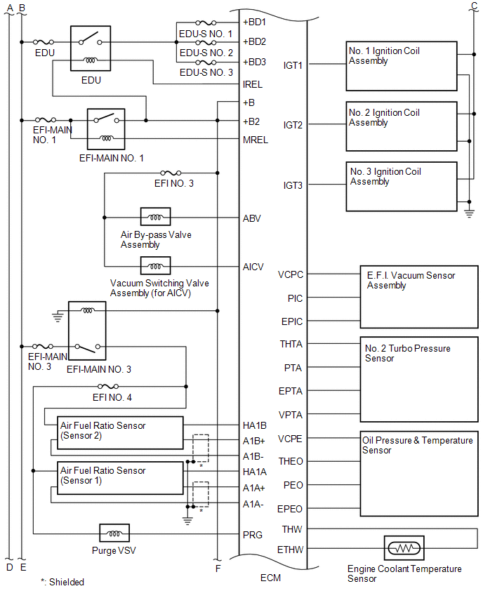
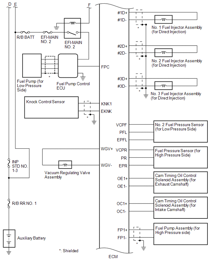
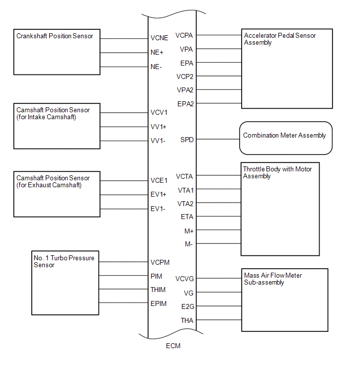
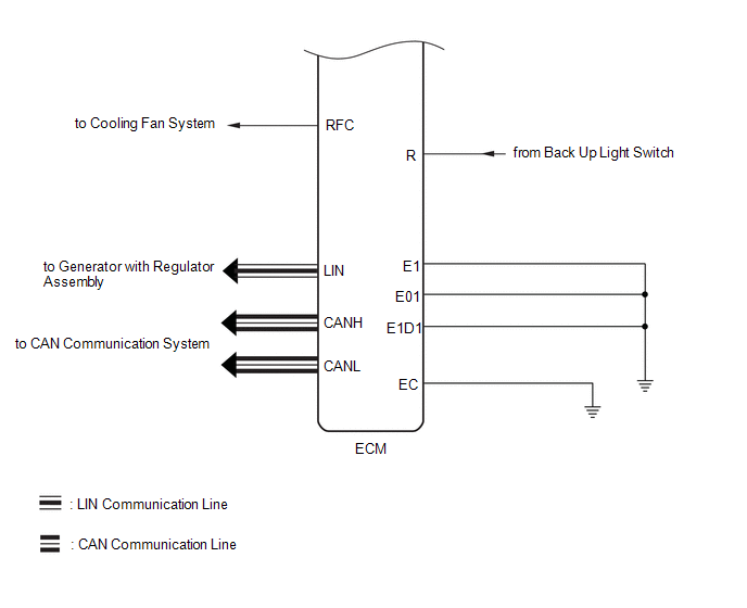
SYSTEM DIAGRAM
 Definition Of Terms
DEFINITION OF TERMS Term Definition Monitor Description Description of what the ECM monitors and how it detects malfunctions (monitoring purpose and details)...
 How To Proceed With Troubleshooting
CAUTION / NOTICE / HINT HINT: *: Use the GTS. PROCEDURE 1. VEHICLE BROUGHT TO WORKSHOP
NEXT
2. CUSTOMER PROBLEM ANALYSIS
NEXT
3...
Other information:
Toyota Yaris XP210 (2020-2026) Reapir and Service Manual: Air Inlet Damper Control Servo Motor Actuator Stuck Off (B143B7F)
DESCRIPTION The No. 1 blower damper servo sub-assembly sends pulse signals to inform the air conditioning amplifier assembly of the damper position. The air conditioning amplifier assembly activates the motor (normal or reverse) based on these signals to move the air inlet damper to the appropriate position, which controls the air inlet switching...
Toyota Yaris XP210 (2020-2026) Reapir and Service Manual: Turbocharger/Supercharger Boost Sensor "A" Circuit Voltage Out of Range (P02351C)
DESCRIPTION Refer to DTC P023511. Click here DTC No. Detection Item DTC Detection Condition Trouble Area MIL Note P02351C Turbocharger/Supercharger Boost Sensor "A" Circuit Voltage Out of Range The discrepancy between the air volume estimated from the No...
Categories
- Manuals Home
- Toyota Yaris Owners Manual
- Toyota Yaris Service Manual
- Power Integration No.1 System Missing Message (B235287,B235587,B235787-B235987)
- Headlights
- Diagnostic Trouble Code Chart
- New on site
- Most important about car
Break-In Period
No special break-in is necessary, but a few precautions in the first 600 miles (1,000 km) may add to the performance, economy, and life of the vehicle.
Do not race the engine. Do not maintain one constant speed, either slow or fast, for a long period of time. Do not drive constantly at full-throttle or high engine rpm for extended periods of time. Avoid unnecessary hard stops. Avoid full-throttle starts.
Copyright © 2026 www.toyaris4.com