Toyota Yaris: Power Integration System / System Description
SYSTEM DESCRIPTION
LOAD OPERATION OUTPUT
(a) Load is turned on or off according to the operation signals and switch signals from each ECU.
| Components | Semiconductor Power Integration ECU | Power Distribution Box Assembly | Operation Signal Communication Support | |
|---|---|---|---|---|
|
*1: w/ Front Seat Heater
*2: Built into power distribution box assembly | ||||
| Headlight ECU Assembly | ○ | - | Not supported | |
| Fog Light Assembly | ○ | - | Supported | |
| Rear Window Defogger / Mirror Heater | - | ○ | Supported | |
| Taillight | - | ○ | Supported | |
| Rear Fog Light | - | ○ | Supported | |
| Back-up Light | - | ○ | Not supported | |
| Outer Rear View Mirror Assembly | - | ○ | Supported | |
| Panel Illumination | - | ○ | Supported | |
| Seat Heater LH*1 | High/Low | - | ○ | Not supported |
| Seat Heater RH*1 | High/Low | - | ○ | Not supported |
| Passenger Seat Buckle Switch Delegated Input | - | ○ | - | |
| Occupant Detection Sensor Delegated Input | - | ○ | - | |
| Rear Seat RH Buckle Switch Delegated Input | - | ○ | - | |
| Rear Seat CTR Buckle Switch Delegated Input | - | ○ | - | |
| Rear Seat LH Buckle Switch Delegated Input | - | ○ | - | |
| IGR Relay*2 | - | ○ | Not supported | |
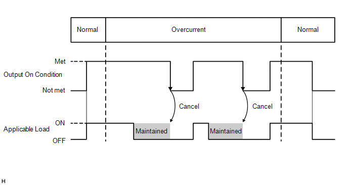
SEMICONDUCTOR FUSE FUNCTION
(a) When a malfunction current occurs during load operation, the current is shut off before the electrical lines emit smoke, and then load is turned off. After the current is shut off, the off condition is maintained until the operation signals or switch signals turn off.
 System Diagram
S..
 How To Proceed With Troubleshooting
CAUTION / NOTICE / HINT HINT:
Use these procedures to troubleshoot the power integration system.
*: Use the GTS.
PROCEDURE 1. VEHICLE BROUGHT TO WORKSHOP
NEXT
2...
Other information:
Toyota Yaris XP210 (2020-2026) Reapir and Service Manual: Removal
REMOVAL CAUTION / NOTICE / HINT HINT: When removing the name plates, heat the vehicle body, back door outside garnish and name plates using a heat light. Heating Temperature Item Temperature Vehicle Body Back Door Panel 40 to 60°C (104 to 140°F) Back Door Outside Garnish Name Plates 20 to 30°C (68 to 86°F) CAUTION: Do not touch the heat light and heated parts, touching the heat light may result in burns...
Toyota Yaris XP210 (2020-2026) Reapir and Service Manual: Vehicle Speed Sensor "A" No Signal (P050031)
DESCRIPTION Vehicles which are equipped with ABS (Anti-lock Brake System) detect the vehicle speed using the skid control ECU (brake actuator assembly) and speed sensors. Each speed sensor monitors the wheel rotation speed and sends a signal to the skid control ECU (brake actuator assembly)...
Categories
- Manuals Home
- Toyota Yaris Owners Manual
- Toyota Yaris Service Manual
- How to connect USB port/Auxiliary jack
- Fuse Panel Description
- Battery Monitor Module General Electrical Failure (P058A01)
- New on site
- Most important about car
Refueling
Before refueling, close all the doors, windows, and the liftgate/trunk lid, and switch the ignition OFF.
To open the fuel-filler lid, pull the remote fuel-filler lid release.
