Toyota Yaris: Stop And Start System / Starter Relay Circuit Current Above Threshold (P061519)
DESCRIPTION
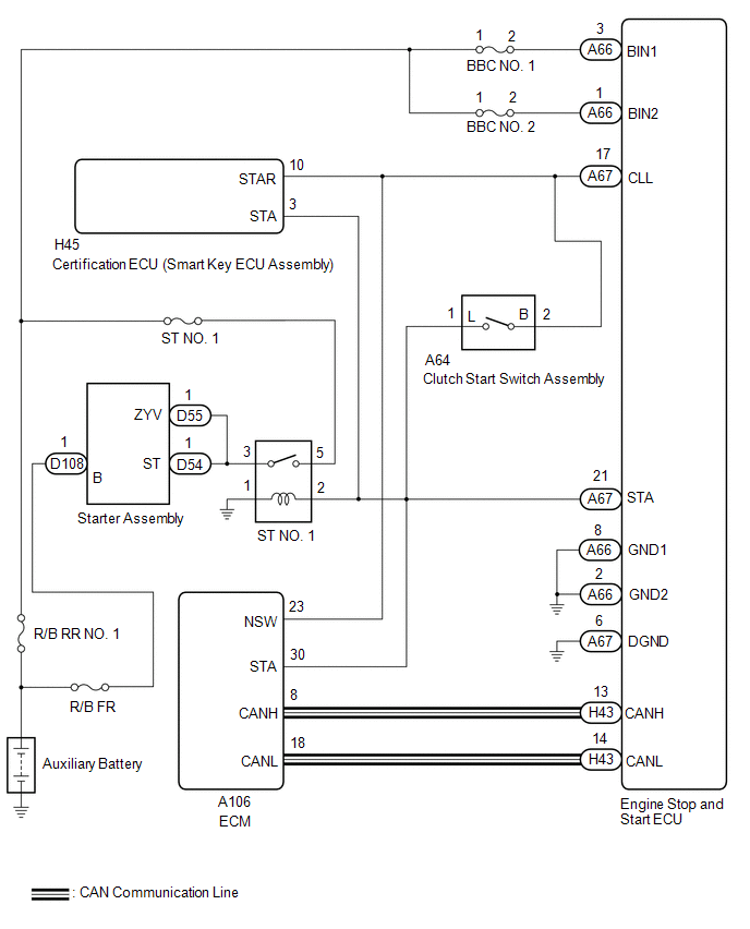
When the engine is started by stop and start control, the engine stop and start ECU controls the starter assembly by activating the ST NO. 1 relay (for starter pinion operation) via voltage from terminal STA.
If overcurrent is detected in the starter relay circuit, the engine stop and start ECU stores DTC P061519 and blinks the stop and start cancel indicator.
| DTC No. | Detection Item | DTC Detection Condition | Trouble Area | Warning Indicate | Memory | Note |
|---|---|---|---|---|---|---|
| P061519 | Starter Relay Circuit Current Above Threshold | Both of the following conditions are met for 1 second (1 trip detection logic):
|
| Blinks | DTC stored | SAE Code: P0617 |
CONFIRMATION DRIVING PATTERN
HINT:
-
If the cable is disconnected from the auxiliary battery terminal, stop and start control is prohibited until refresh charge is completed.
In this case, let the vehicle idle to complete the refresh charge. The refresh charge is complete when the Data List item Status of Auxiliary Battery Charge Control changes from "Refresh Charge Mode". (Usually, idling the engine for 5 to 60 minutes with the auxiliary battery fluid temperature at 11°C (52°F) or higher, the refresh charge will be completed.)
-
If the GTS is not available and the Data List item Status of Auxiliary Battery Charge Control cannot be checked, charge the auxiliary battery by idling the engine for approximately 5 to 60 minutes or driving the vehicle, and then drive the vehicle and check that stop and start control operates.
If the engine is started with the hood open, the system determines that a jump start has occurred. Therefore, make sure that the hood is closed before starting the engine and driving the vehicle.
- After the refresh charge completes, turn the ignition switch off, wait for at least 30 seconds, and then start the engine again. If the vehicle enters refresh charge mode again while the engine is idling, the initial refresh charge did not properly complete, so wait for the refresh charge to complete.
- Allow the engine to idle for 3 minutes after it is warmed up and check that the engine idle speed is within 50 rpm of the target idle speed.
CONFIRMATION AFTER TROUBLESHOOTING
(a) Clear the DTCs.
Powertrain > Stop and Start > Clear DTCs(b) Start the engine and warm it up.
(c) Drive the vehicle at 7 km/h (4 mph) or more.
CAUTION:
When performing Confirmation Driving Pattern, obey all speed limits and traffic laws.
(d) Stop the vehicle, move the shift lever to neutral and release the clutch pedal.
(e) Keep the engine stopped by stop and start control for 1 second or more.
(f) Depress the clutch pedal and start the engine.
(g) Check that DTCs are not output.
Powertrain > Stop and Start > Trouble CodesSTOP AND START SYSTEM OPERATION CHECK
Click here

WIRING DIAGRAM
CAUTION / NOTICE / HINT
NOTICE:
-
Before replacing the engine stop and start ECU, read the number of starter operations and write it into a new engine stop and start ECU.
Click here

-
After replacing the engine stop and start ECU, perform learning of the external backup boost converter (eco run vehicle converter assembly).
Click here

-
After replacing the engine stop and start ECU or air conditioning amplifier assembly, reset and perform learning of the air conditioning information in the engine stop and start ECU.
Click here

- Inspect the fuses for circuits related to this system before performing the following procedure.
HINT:
-
Using the GTS, read the freeze frame data before troubleshooting. System condition information is recorded as freeze frame data the moment a DTC is stored. This information can be useful when troubleshooting.
Click here

-
For wire harness and connector inspection procedures and precautions, refer to "
 "
"
-
DTCs for the stop and start system are not cleared even if the malfunction has been repaired. After repairing the malfunction, be sure to clear the DTCs.
Click here

PROCEDURE
| 1. | CHECK HARNESS AND CONNECTOR (ENGINE STOP AND START ECU - BBC NO. 1 FUSE AND BBC NO. 2 FUSE) |
(a) Disconnect the A66 engine stop and start ECU connector.
(b) Remove the BBC NO. 1 fuse and BBC NO. 2 fuse from the No. 1 engine room relay block.
(c) Measure the resistance according to the value(s) in the table below.
Standard Resistance:
| Tester Connection | Condition | Specified Condition |
|---|---|---|
| A66-1 (BIN2) - 2 (BBC NO. 2 fuse) | Always | Below 1 Ω |
| A66-3 (BIN1) - 2 (BBC NO. 1 fuse) | Always | Below 1 Ω |
| A66-1 (BIN2) - Body ground and other terminals | Always | 10 kΩ or higher |
| A66-3 (BIN1) - Body ground and other terminals | Always | 10 kΩ or higher |
| 2 (BBC NO. 2 fuse) - Body ground and other terminals | Always | 10 kΩ or higher |
| 2 (BBC NO. 1 fuse) - Body ground and other terminals | Always | 10 kΩ or higher |
| NG |
 | REPAIR OR REPLACE HARNESS OR CONNECTOR |
|

| 2. | CHECK HARNESS AND CONNECTOR (ENGINE STOP AND START ECU - ST NO. 1 RELAY) |
(a) Disconnect the H45 certification ECU (smart key ECU assembly) connector.
(b) Disconnect the A64 clutch start switch assembly connector.
(c) Disconnect the A106 ECM connector.
(d) Disconnect the A66 and A67 engine stop and start ECU connectors.
(e) Remove the ST NO. 1 relay from the No. 1 engine room relay block.
(f) Measure the resistance according to the value(s) in the table below.
Click here

Standard Resistance:
| Tester Connection | Condition | Specified Condition |
|---|---|---|
| A67-21 (STA) - 2 (ST NO. 1 relay holder) | Always | Below 1 Ω |
| A67-21 (STA) - Body ground and other terminals | Always | 10 kΩ or higher |
| 2 (ST NO. 1 relay holder) - Body ground and other terminals | Always | 10 kΩ or higher |
| A66-1 (BIN2) - A67-21 (STA) | Always | 10 kΩ or higher |
| A66-3 (BIN1) - A67-21 (STA) | Always | 10 kΩ or higher |
| NG |
 | REPAIR OR REPLACE HARNESS OR CONNECTOR |
|

| 3. | CHECK ENGINE STOP AND START ECU |
(a) Disconnect the engine stop and start ECU connector.
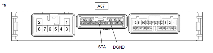
| *a | Component without harness connected (Engine Stop and Start ECU) | - | - |
(b) Measure the resistance according to the value(s) in the table below.
Standard Resistance:
| Tester Connection | Condition | Specified Condition |
|---|---|---|
| A67-21 (STA) - A67-6 (DGND) | Always | 10 kΩ or higher |
| NG |
 | REPLACE ENGINE STOP AND START ECU |
|

| 4. | INSPECT RELAY (ST NO. 1 RELAY) |
(a) Inspect the ST NO. 1 relay.
Click here

| OK |
 | USE SIMULATION METHOD TO CHECK |
| NG |
 | REPLACE RELAY (ST NO. 1 RELAY) |
 Analog to Digital Converter Circuit Voltage Out of Range (P060B1C,P060B49,P060B71)
DESCRIPTION If an internal malfunction occurs in the engine stop and start ECU, it stores P060B1C, P060B49 or P060B71 and blinks the stop and start cancel indicator...
 Starter Relay Signal Compare Failure (P061562)
DESCRIPTION When the STA signal detected by the ECM and by the engine stop and start ECU do not match, the engine stop and start ECU stores DTC P061562 and blinks the stop and start cancel indicator...
Other information:
Toyota Yaris XP210 (2020-2026) Owner's Manual: Manual Shift Mode
The manual shift mode gives you the feel of driving a manual transaxle vehicle by allowing you to operate the selector lever manually. This allows you to control engine rpm and torque to the drive wheels much like a manual transaxle when more control is desired...
Toyota Yaris XP210 (2020-2026) Reapir and Service Manual: Removal
REMOVAL CAUTION / NOTICE / HINT The necessary procedures (adjustment, calibration, initialization, or registration) that must be performed after parts are removed, installed, or replaced during the air fuel ratio sensor removal/installation are shown below...
Categories
- Manuals Home
- Toyota Yaris Owners Manual
- Toyota Yaris Service Manual
- Auto Lock/Unlock Function
- Fuse Panel Description
- Diagnostic Trouble Code Chart
- New on site
- Most important about car
Refueling
Before refueling, close all the doors, windows, and the liftgate/trunk lid, and switch the ignition OFF.
To open the fuel-filler lid, pull the remote fuel-filler lid release.
