Toyota Yaris: Light Bulbs / Replacing Interior Light Bulbs
Toyota Yaris XP210 (2020-2026) Owner's Manual / Maintenance and Care / Owner Maintenance / Light Bulbs / Replacing Interior Light Bulbs
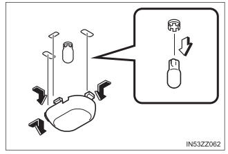
Overhead lights/Map lights
- Wrap a small flathead screwdriver with a soft cloth to prevent damage to the lens, and then remove the lens by carefully prying on the edge of the lens with the flathead screwdriver.
- Disconnect the bulb by pulling it out.
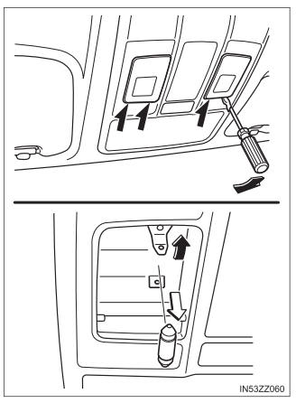
- Install the new bulb in the reverse order of the removal procedure.
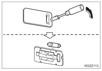
Trunk light (4-Door)
- Press both sides of the lens cap to remove it.
- Disconnect the bulb by pulling it out.
- Install the new bulb in the reverse order of the removal procedure.
Luggage compartment light (5-Door)
- Wrap a small flathead screwdriver with a soft cloth to prevent damage to the lens and remove the lens by carefully prying on the edge of the lens with the flathead screwdriver.
- Disconnect the bulb by pulling it out.
- Install the new bulb in the reverse order of the removal procedure.
 Replacing Exterior Light Bulbs
Headlights/Daytime running lights (With halogen headlights)
Make sure the ignition is switched off, and the headlight switch is
off.
Lift the hood...
 Fuses
Fuses
Your vehicle’s electrical system is protected by fuses.
If any lights, accessories, or controls do not work, inspect the
appropriate circuit protector...
Other information:
Toyota Yaris XP210 (2020-2026) Reapir and Service Manual: Components
COMPONENTS ILLUSTRATION *A for Driver Side *B for Front Passenger Side *1 FRONT SEAT VERTICAL ADJUSTER HANDLE *2 NO.1 RECLINING HINGE COVER *3 RECLINING ADJUSTER RELEASE HANDLE *4 SEAT ADJUSTER COVER CAP *5 FRONT SEAT CUSHION SHIELD *6 FRONT SEAT INNER CUSHION SHIELD ILLUSTRATION *1 SEPARATE TYPE FRONT SEATBACK ASSEMBLY - - Tightening torque for "Major areas involving basic vehicle performance such as moving/turning/stopping" : N*m (kgf*cm, ft...
Toyota Yaris XP210 (2020-2026) Reapir and Service Manual: Terminals Of Ecu
TERMINALS OF ECU TERMINALS OF ECU *a Component without harness connected (Skid Control ECU [Brake Actuator Assembly]) - - Terminal No. (Symbol) Terminal Description 1 (GND2) Pump motor ground 2 - (Not used) 3 - (Not used) 4 - (Not used) 5 (STP2) Stop light switch assembly input 6 - (Not used) 7 - (Not used) 8 - (Not used) 9 - (Not used) 10 (CANL) CAN communication line L 11 - (Not used) 12 (IGR) ECU power supply input 13 (BM) Motor relay power supply 14 (SP1) Speed signal output for speedometer 15 (RR-) Rear wheel speed RH (-) signal input 16 (RR+) Rear wheel speed RH (+) power supply output 17 (FL-) Front wheel speed LH (-) signal input 18 (FL+) Front wheel speed LH (+) power supply output 19 - (Not used) 20 - (Not used) 21 - (Not used) 22 (CANH) CAN communication line H 23 - (Not used) 24 - (Not used) 25 (GND1) Skid control ECU (brake actuator assembly) ground 26 (STPO) Stop light switch assembly output 27 - (Not used) 28 (RL-) Rear wheel speed LH (-) signal input 29 (RL+) Rear wheel speed LH (+) power supply output 30 (FR-) Front wheel speed RH (-) signal input 31 (FR+) Front wheel speed RH (+) power supply output 32 - (Not used) 33 (CSW) VSC OFF switch (combination switch assembly) input 34 - (Not used) 35 (STP) Stop light switch assembly input 36 (CA2H) CAN communication line H 37 (CA2L) CAN communication line L 38 (+BS) Solenoid relay power supply TERMINAL INSPECTION (a) Disconnect the A108 connector and measure the voltage or resistance on the wire harness side...
Categories
- Manuals Home
- Toyota Yaris Owners Manual
- Toyota Yaris Service Manual
- Key Battery Replacement
- Brake System Control Module "A" System Voltage System Voltage Low (C137BA2)
- Removal
- New on site
- Most important about car
Front Seat Belt Pretensioners
The front seat belt pretensioners are designed to deploy in moderate or severe frontal, near frontal collisions.
In addition, the pretensioners operate when a side collision or a rollover accident is detected. The pretensioners operate differently depending on what types of air bags are equipped. For more details about the seat belt pretensioner operation, refer to the SRS Air Bag Deployment Criteria.
Copyright © 2026 www.toyaris4.com