Toyota Yaris: Air Conditioning Unit / Removal
REMOVAL
CAUTION / NOTICE / HINT
The necessary procedures (adjustment, calibration, initialization, or registration) that must be performed after parts are removed, installed, or replaced during the air conditioner unit assembly removal/installation are shown below.
Necessary Procedure After Parts Removed/Installed/Replaced| Replacement Part or Procedure | Necessary Procedures | Effects/Inoperative when not performed | Link |
|---|---|---|---|
| No. 1 air conditioning radiator damper servo sub-assembly | Initialize servo motor (Air Conditioning System) | DTCs are stored |
|
| Air conditioning amplifier assembly |
| Engine start function |
|
| Initialize servo motor (Air Conditioning System) | DTCs are stored |
|


HINT:
When the cable is disconnected / reconnected to the auxiliary battery terminal, systems temporarily stop operating. However, each system has a function that completes learning the first time the system is used.
-
Learning completes when vehicle is driven
Effect/Inoperative Function When Necessary Procedures are not Performed
Necessary Procedures
Link
Lane tracing assist system
Drive the vehicle straight ahead at 35 km/h (22 mph) or more for 5 second or more.

Pre-collision system
Stop and start system
Drive the vehicle until stop and start control is permitted (approximately 5 to 60 minutes)

-
Learning completes when vehicle is operated normally
Effect/Inoperative Function When Necessary Procedures are not Performed
Necessary Procedures
Link
Power door lock control system
- Back door opener
Perform door unlock operation with door control switch or electrical key transmitter sub-assembly switch.

Air conditioning system
After the ignition switch is turned to ON, the servo motor standard position is recognized.
-
PROCEDURE
1. RECOVER REFRIGERANT FROM REFRIGERATION SYSTEM
Click here

2. REMOVE NO. 1 ENGINE UNDER COVER ASSEMBLY
Click here

3. DRAIN ENGINE COOLANT
Click here

4. REMOVE WINDSHIELD WIPER MOTOR AND LINK
Click here

5. REMOVE WATER GUARD PLATE RH
| (a) Disengage the claws to remove the water guard plate RH. |
|
6. REMOVE NO. 1 FRONT VENTILATOR SEAL
| (a) Disengage the claws to remove the No. 1 front ventilator seal. |
|
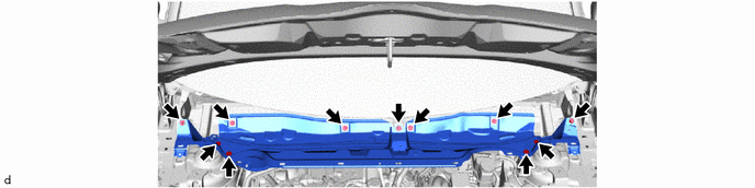
7. REMOVE OUTER COWL TOP PANEL SUB-ASSEMBLY
| (a) Disengage the clamp. |
|
(b) Remove the 11 bolts and outer cowl top panel sub-assembly.
8. REMOVE DASH PANEL HEAT INSULATOR
Click here

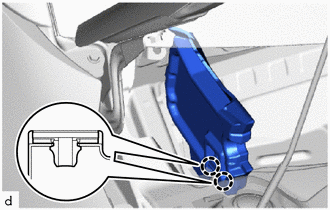
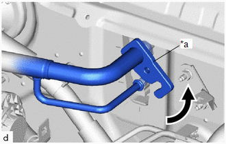
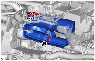
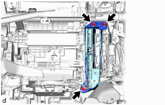
9. DISCONNECT AIR CONDITIONING TUBE AND ACCESSORY ASSEMBLY
| (a) Remove the bolt. |
|
| (b) Rotate the hook connector to disconnect the No. 2 air conditioning tube and accessory assembly as shown in the illustration. |
|
(c) Remove the 2 O-rings from the No. 2 air conditioning tube and accessory assembly.
NOTICE:
Seal the openings of the disconnected parts using vinyl tape to prevent entry of moisture and foreign matter.
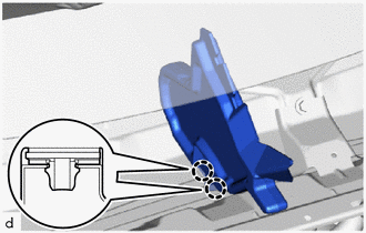
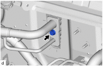
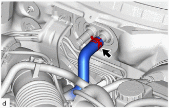
10. DISCONNECT OUTLET HEATER WATER HOSE
| (a) Slide the hose clip to disconnect the outlet heater water hose. NOTICE:
|
|
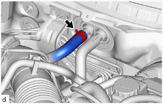
11. DISCONNECT INLET HEATER WATER HOSE
| (a) Slide the hose clip to disconnect the inlet heater water hose. NOTICE:
|
|
12. REMOVE INSTRUMENT PANEL ASSEMBLY
Click here

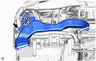
13. REMOVE NO. 1 AIR DUCT
| (a) Disengage the clamps. |
|

(b) Remove the 2 bolts.
(c) Disengage the claws to remove the No. 1 air duct.
14. REMOVE STEERING COLUMN ASSEMBLY
Click here

15. REMOVE CENTER HEATER TO REGISTER DUCT SUB-ASSEMBLY
| (a) Remove the clip. |
|
(b) Disengage the clamp to remove the center heater to register duct sub-assembly.
16. REMOVE NO. 1 HEATER TO REGISTER DUCT SUB-ASSEMBLY
| (a) Remove the clip. |
|
(b) Disengage the clamp to remove the No. 1 heater to register duct sub-assembly.
17. REMOVE NO. 2 HEATER TO REGISTER DUCT SUB-ASSEMBLY
| (a) Remove the clip. |
|
(b) Disengage the clamps to remove the No. 2 heater to register duct sub-assembly.
18. REMOVE FRONT SEAT ASSEMBLY LH
Click here

19. REMOVE FRONT SEAT ASSEMBLY RH
HINT:
Use the same procedure as for the LH side.
20. SEPARATE FRONT FLOOR CARPET ASSEMBLY
(a) Remove the 2 clips to turn back the front floor carpet assembly as shown in the illustration.
21. REMOVE NO. 4 DASH PANEL INSULATOR PAD
(a) Cut each claw of the 2 clips and remove the No. 4 dash panel insulator pad.

| *a | Cut | - | - |
NOTICE:
If the No. 4 dash panel insulator pad is damaged, replace it with a new one.
(b) Remove the 2 clips.
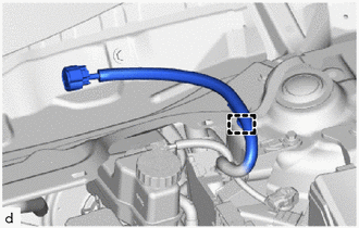
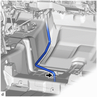
22. DISCONNECT DRAIN COOLER HOSE
| (a) Disconnect the drain cooler hose. |
|
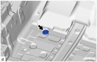
23. REMOVE COOLER UNIT DRAIN HOSE GROMMET
| (a) Remove the cooler unit drain hose grommet. NOTICE: If the drain cooler hose is disconnected from the cooler unit drain hose grommet, make sure to replace the cooler unit drain hose grommet with a new one. Failure to do so may lead to water ingress. |
|
24. REMOVE METER MIRROR SUB-ASSEMBLY (w/ Headup Display)
Click here

25. REMOVE NO. 3 INSTRUMENT PANEL TO COWL BRACE SUB-ASSEMBLY
Click here

26. REMOVE POWER DISTRIBUTION BOX ASSEMBLY WITH MULTIPLEX NETWORK BODY ECU
Click here

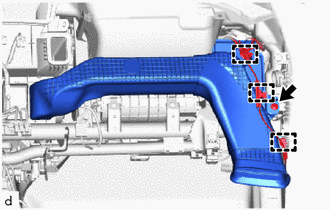
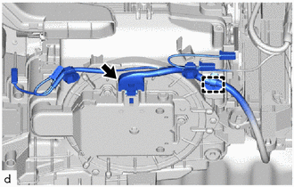
27. REMOVE NO. 1 INSTRUMENT PANEL BRACE SUB-ASSEMBLY
| (a) Remove the bolt to disconnect the instrument panel wire. |
|
(b) Disengage the clamps to disconnect the instrument panel wire.
(c) Remove the bolt, screw, nut and No.1 instrument panel brace sub-assembly.
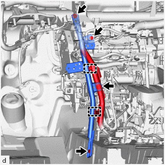
28. SEPARATE INSTRUMENT PANEL WIRE
| (a) Disengage the clamps. |
|
| (b) Remove the 2 nuts and bolt to separate the ECU integration box RH. |
|
| (c) Disconnect the connector. |
|
(d) Disengage the clamp.
(e) Disconnect each connector.
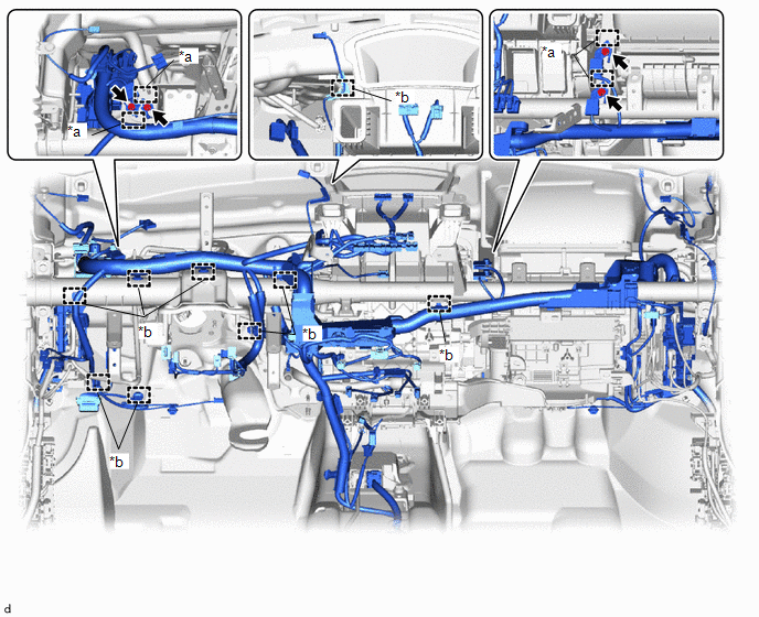
| *a | Guide | *b | Clamp |
(f) Remove the 4 ground wire bolts.
(g) Disengage the guides to disconnect the 4 ground wires.
(h) Disengage the clamps to separate the instrument panel wire.
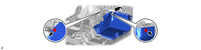
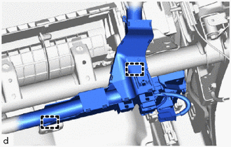
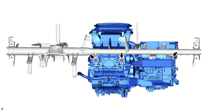
29. REMOVE INSTRUMENT PANEL REINFORCEMENT ASSEMBLY WITH AIR CONDITIONER UNIT ASSEMBLY
(a) Remove the nut and 6 bolts.
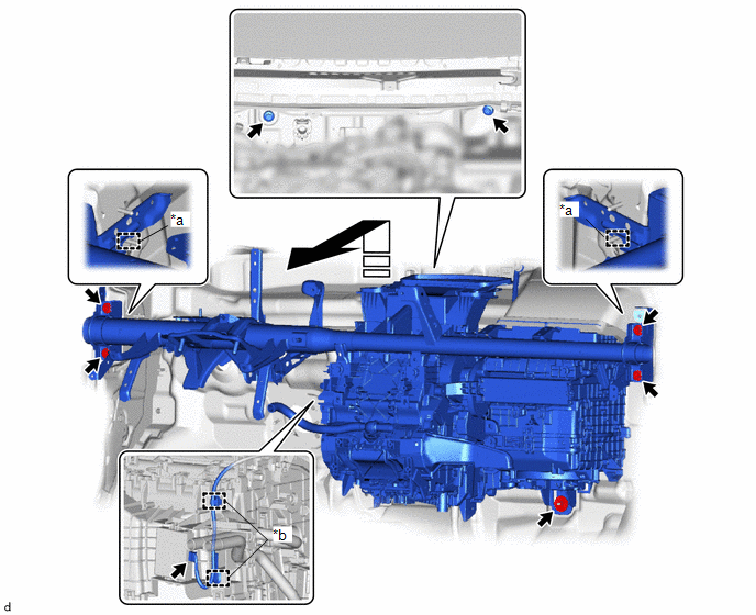
| *a | Guide | *b | Clamp |
 | Remove in this Direction | - | - |
(b) Disengage the guides to separate the instrument panel reinforcement assembly with air conditioner unit assembly as shown in the illustration.
(c) Disengage the clamps.
(d) Disconnect the connector to remove the instrument panel reinforcement assembly with air conditioner unit assembly.
30. REMOVE AIR CONDITIONER UNIT ASSEMBLY
(a) Remove the 3 bolts and air conditioner unit assembly.
 Components
COMPONENTS ILLUSTRATION
*1 NO. 1 ENGINE UNDER COVER ASSEMBLY - -
N*m (kgf*cm, ft.*lbf): Specified torque - - ILLUSTRATION
*1 WATER GUARD PLATE RH *2 NO...
 Disassembly
DISASSEMBLY PROCEDURE 1. REMOVE LOWER DEFROSTER NOZZLE ASSEMBLY (a) Disengage the claws and guides to remove the lower defroster nozzle assembly.
2...
Other information:
Toyota Yaris XP210 (2020-2026) Reapir and Service Manual: Components
C..
Toyota Yaris XP210 (2020-2026) Reapir and Service Manual: Lost Communication with Brake System Control Module Missing Message (U012987)
MONITOR DESCRIPTION The ECM and skid control ECU (brake actuator assembly) send and receive signals via CAN communication. If a communication error occurs between the ECM and skid control ECU (brake actuator assembly), the ECM stores this DTC. DTC No...
Categories
- Manuals Home
- Toyota Yaris Owners Manual
- Toyota Yaris Service Manual
- Battery Monitor Module General Electrical Failure (P058A01)
- Headlights
- Adjustment
- New on site
- Most important about car
Supplemental Restraint System (SRS) Precautions
The front and side supplemental restraint systems (SRS) include different types of air bags. Please verify the different types of air bags which are equipped on your vehicle by locating the “SRS AIRBAG” location indicators. These indicators are visible in the area where the air bags are installed.
The air bags are installed in the following locations:
The steering wheel hub (driver air bag) The front passenger dashboard (front passenger air bag) The outboard sides of the front seatbacks (side air bags) The front and rear window pillars, and the roof edge along both sides (curtain air bags)