Toyota Yaris: Climate Control System / Operating Tips
Toyota Yaris XP210 (2020-2026) Owner's Manual / Interior Features / Climate Control System / Operating Tips
- Operate the climate control system with the engine running.
- To prevent the battery from being discharged, do not leave the fan control dial on for a long period of time with the ignition switched ON when the engine is not running.
- Clear all obstructions such as leaves, snow and ice from the hood and the air inlet in the cowl grille to improve the system efficiency.
- Use the climate control system to defog the windows and dehumidify the air.
- The recirculate mode should be used when driving through tunnels or while in a traffic jam, or when you would like to shut off outside air for quick cooling of the interior.
- Use the outside air position for ventilation or windshield defrosting.
- If the vehicle has been parked in direct sunlight during hot weather, open the windows to let warm air escape, then run the climate control system.
- Run the air conditioner about 10 minutes at least once a month to keep internal parts lubricated.
- Have the air conditioner checked before the weather gets hot. Lack
of refrigerant may make the air conditioner less efficient.
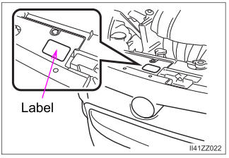
The refrigerant specifications are indicated on a label attached to the inside of the engine compartment. Check the label before refilling the refrigerant. If the wrong type of refrigerant is used, it could result in a serious malfunction of the air conditioner.
For details, consult your Toyota dealer.


Other information:
Toyota Yaris XP210 (2020-2026) Reapir and Service Manual: How To Proceed With Troubleshooting
CAUTION / NOTICE / HINT NOTICE: Because the order of diagnosis is important to allow correct diagnosis, make sure to begin troubleshooting using How to Proceed with Troubleshooting when CAN communication system related DTCs are output. If the CAN communication system is malfunctioning, check the contact pressure of the terminals in connectors, as insufficient terminal contact pressure may be the cause...
Toyota Yaris XP210 (2020-2026) Reapir and Service Manual: High Pressure Fuel Pump Circuit Open (P123513)
DESCRIPTION The high-pressure direct injection fuel system consists of a spill control valve, check valve, fuel relief valve, fuel pressure sensor (for high pressure side), fuel pump assembly (for high pressure side) and direct fuel injector assemblies...
Categories
- Manuals Home
- Toyota Yaris Owners Manual
- Toyota Yaris Service Manual
- Immobilizer System
- Auto Lock/Unlock Function
- Diagnostic Trouble Code Chart
- New on site
- Most important about car
Supplemental Restraint System (SRS) Precautions
The front and side supplemental restraint systems (SRS) include different types of air bags. Please verify the different types of air bags which are equipped on your vehicle by locating the “SRS AIRBAG” location indicators. These indicators are visible in the area where the air bags are installed.
The air bags are installed in the following locations:
The steering wheel hub (driver air bag) The front passenger dashboard (front passenger air bag) The outboard sides of the front seatbacks (side air bags) The front and rear window pillars, and the roof edge along both sides (curtain air bags)
Copyright © 2026 www.toyaris4.com