Toyota Yaris: Engine / On-vehicle Inspection
ON-VEHICLE INSPECTION
CAUTION / NOTICE / HINT
CAUTION:
-
When working near the engine room while the engine has started or the power source mode is engine switch on (IG), do not touch the fan and generator V belt or rotating components such as the fan, etc.
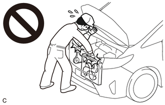
- Touching the fan and generator V belt or rotating components such as the fan, etc. could result in your hand or clothing getting caught and pulled in.
PROCEDURE
1. INSPECT ENGINE COOLANT
Click here

2. INSPECT ENGINE OIL
Click here

3. INSPECT AUXILIARY BATTERY CONDITION
Click here

4. INSPECT SPARK PLUG
Click here

5. INSPECT AIR CLEANER FILTER ELEMENT SUB-ASSEMBLY
(a) Remove the air cleaner filter element sub-assembly.
Click here

(b) Visually check that the air cleaner filter element sub-assembly is not damaged or excessively oily. If necessary, replace the air cleaner filter element sub-assembly.
HINT:
- If there is any dirt or clogs in the air cleaner filter element sub-assembly, clean it with compressed air.
- If any dirt or clogs remain even after cleaning the air cleaner filter element sub-assembly with compressed air, replace it.
(c) Install the air cleaner filter element sub-assembly.
Click here

6. INSPECT FAN AND GENERATOR V BELT
Click here

7. INSPECT V-RIBBED BELT TENSIONER ASSEMBLY
(a) Remove the fan and generator V belt.
Click here

(b) Turn the V-ribbed belt tensioner assembly clockwise and counterclockwise and check that it turns smoothly and does not catch.
HINT:
If the V-ribbed belt tensioner assembly does not turn smoothly or catches, replace the V-ribbed belt tensioner assembly.
(c) Install the fan and generator V belt.
Click here

8. INSPECT VALVE LASH ADJUSTER ASSEMBLY NOISE
(a) Rev up the engine several times. Check that the engine does not emit unusual noises.
(b) If unusual noises occur, warm up the engine and idle it for 30 minutes or more, then perform the inspection.
HINT:
If any defects or problems are found during the inspection, perform the valve lash adjuster assembly inspection.
Click here

9. INSPECT IGNITION TIMING
NOTICE:
- Check the ignition timing with the cooling fan off.
- Turn off all electrical systems and the A/C.
- When checking the ignition timing, the transaxle should be in neutral or park.
(a) Warm up and stop the engine.
(b) Connect the GTS to the DLC3.
(c) Start the engine and run it at idle.
(d) Turn the GTS on.
(e) Enter the following menus: Powertrain / Engine / Data List / Ignition Timing Cylinder #1.
Powertrain > Engine > Data List| Tester Display |
|---|
| Ignition Timing Cylinder #1 |
Standard Ignition Timing:
| Condition | Specified Condition |
|---|---|
| Idle speed | -5 to 15°CA BTDC |
(f) Enter the following menus: Powertrain / Engine / Active Test / Activate the TC Terminal / ON.
Powertrain > Engine > Active Test| Active Test Display |
|---|
| Activate the TC Terminal |
| Data List Display |
|---|
| Ignition Timing Cylinder #1 |
(g) Monitor Ignition Timing Cylinder #1 of the Data List.
Standard Ignition Timing:
| Condition | Specified Condition |
|---|---|
| Idle speed | 8 to 12°CA BTDC |
(h) Enter the following menus: Powertrain / Engine / Active Test / Activate the TC Terminal / OFF.
(i) Check that the ignition timing advances immediately when the engine speed is increased.
10. INSPECT ENGINE IDLE SPEED
NOTICE:
- Check the ignition timing with the cooling fan off.
- Turn off all electrical systems and the A/C.
- When checking the ignition timing, the transaxle should be in neutral or park.
(a) Warm up and stop the engine.
(b) Connect the GTS to the DLC3.
(c) Start the engine and run it at idle.
(d) Turn the GTS on.
(e) Enter the following menus: Powertrain / Engine / Data List / Engine Speed.
Powertrain > Engine > Data List| Tester Display |
|---|
| Engine Speed |
(f) Read the value displayed on the tester.
Standard Idle Speed:
| Condition | Specified Condition |
|---|---|
| N Position | 950 to 1050 rpm |
11. INSPECT COMPRESSION
NOTICE:
Keep the spark plug holes free of foreign matter when measuring the compression pressure.
(a) Warm up and stop the engine.
(b) Check for DTCs.
Click here

(c) Remove the 3 spark plugs.
Click here

(d) Disconnect the No. 5 engine wire connector.
(e) Disconnect the No. 6 engine wire connector.
(f) Check the cylinder compression pressure.
(1) Insert a compression gauge into the spark plug hole.
(2) Fully open the throttle.
(3) While cranking the engine, measure the compression pressure.
Standard Compression Pressure:
| Item | Minimum Compression Pressure | Standard Compression Pressure |
|---|---|---|
| No.1 Cylinder | 980 kPa 10.0 kgf/cm2 142 psi | 1300 kPa 13.3 kgf/cm2 189 psi |
| No.2 Cylinder | 980 kPa 10.0 kgf/cm2 142 psi | 1300 kPa 13.3 kgf/cm2 189 psi |
| No.3 Cylinder | 980 kPa 10.0 kgf/cm2 142 psi | 1300 kPa 13.3 kgf/cm2 189 psi |
| Pressure Difference between Each Cylinder | - | 200 kPa or less 2.0 kgf/cm2 or less 29 psi or less |
NOTICE:
- Always use a fully charged auxiliary battery to obtain an engine speed of 250 rpm or more.
- Inspect all cylinders in the same way.
- Measure the compression pressure as quickly as possible.
(4) If the cylinder compression pressure is low, pour a small amount of engine oil into the cylinder through the spark plug hole and inspect it again.
HINT:
- If adding oil increases the compression pressure, the piston rings and/or cylinder bore may be worn or damaged.
- If the compression pressure stays low, a valve may be stuck or seated improperly, or there may be leaks in the cylinder head gasket.
(g) Connect the No. 6 engine wire connector.
(h) Connect the No. 5 engine wire connector.
(i) Install the 3 spark plugs.
Click here

(j) Clear the DTCs.
Click here

NOTICE:
After the inspection, clear the DTCs, check for DTCs again and make sure the normal system code is output.
12. INSPECT CO/HC
HINT:
This check determines whether or not the idle CO/HC complies with regulations.
(a) Start the engine.
(b) Run the engine at 2500 rpm for approximately 180 seconds.
(c) Insert a CO/HC meter testing probe at least 40 cm (1.31 ft.) into the tailpipe during idle.
(d) Immediately check the CO/HC concentration during idle and when the engine is running at 2500 rpm.
HINT:
When performing a 2 mode (with the engine idling/running at 2500 rpm) test, the measurement procedures are determined by applicable local regulations.
If the CO/HC concentration does not comply with the regulations, perform troubleshooting in the order given below.
(1) Check for DTCs.
Click here

(2) See the following table for possible causes, then inspect the applicable parts and repair them if necessary.
| CO | HC | Problem | Cause |
|---|---|---|---|
| Normal | High | Rough idle |
|
| Low | High | Rough idle (Fluctuating HC reading) |
|
| High | High | Rough idle (Black smoke from exhaust) |
|
 Engine
..

Other information:
Toyota Yaris XP210 (2020-2026) Reapir and Service Manual: 4wd Control Switch
ComponentsCOMPONENTS ILLUSTRATION *1 CONSOLE BOX ASSEMBLY *2 4WD CONTROL SWITCH (NO. 2 COMBINATION SWITCH ASSEMBLY) RemovalREMOVAL PROCEDURE 1. REMOVE CONSOLE BOX ASSEMBLY Click here 2. REMOVE 4WD CONTROL SWITCH (NO. 2 COMBINATION SWITCH ASSEMBLY) (a) Remove the 3 screws and 4WD control switch (No...
Toyota Yaris XP210 (2020-2026) Reapir and Service Manual: Rear Seat Belt Warning Light Malfunction
DESCRIPTION The main body ECU (multiplex network body ECU) detects whether either the rear doors are open or closed based on the courtesy light switch condition and then sends the rear door status signal to the combination meter assembly. The power distribution box assembly detects whether either the rear seat belts are fastened or unfastened based on the rear seat belt buckle switch condition and then sends the rear seat belt buckle switch status signal to the combination meter assembly...
Categories
- Manuals Home
- Toyota Yaris Owners Manual
- Toyota Yaris Service Manual
- Key Battery Replacement
- Power Integration No.1 System Missing Message (B235287,B235587,B235787-B235987)
- How to use USB mode
- New on site
- Most important about car
Fuel Gauge
The fuel gauge shows approximately how much fuel is remaining in the tank when the ignition is switched ON. We recommend keeping the tank over 1/4 full.
