Toyota Yaris: Vehicle Stability Control System / Left Front Wheel Speed Sensor Signal Stuck Low (C050023)
DESCRIPTION
Refer to DTC C05001F.
Click here

| DTC No. | Detection Item | DTC Detection Condition | Trouble Area | DTC Output from |
|---|---|---|---|---|
| C050023 | Left Front Wheel Speed Sensor Signal Stuck Low | Any of the following is detected:
|
| Brake |
WIRING DIAGRAM
Refer to DTC C05001F.
Click here

CAUTION / NOTICE / HINT
NOTICE:
-
After replacing or removing and installing a speed sensor, perform Dealer Mode (Signal Check) inspection to confirm that the speed sensors are operating correctly.
Click here

-
After replacing or removing a speed sensor rotor, perform Dealer Mode (Signal Check) inspection to confirm that the speed sensors are operating correctly.
Click here

PROCEDURE
| 1. | CHECK FRONT SPEED SENSOR LH INSTALLATION |
| (a) Turn the ignition switch off. |
|
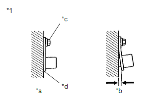
(b) Check the front speed sensor LH installation.
OK:
There is no clearance between the front speed sensor LH and front axle carrier sub-assembly.
The installation bolt is tightened properly.
Torque
8.5 N*m (87 kgf*cm, 75 in.*lbf)
| NG |
 | REINSTALL OR REPLACE FRONT SPEED SENSOR LH |
|

| 2. | CHECK FRONT SPEED SENSOR LH (CHECK FOR FOREIGN MATTER) |
(a) Remove the front speed sensor LH.
Click here

(b) Check the front speed sensor LH tip.
OK:
The front speed sensor LH tip is free of scratches, oil, and foreign matter.
NOTICE:
- If there is oil or foreign matter on the front speed sensor LH, clean the front speed sensor LH.
- If the front speed sensor LH is damaged, replace the front speed sensor LH with a new one.
| NG |
 | CLEAN OR REPLACE FRONT SPEED SENSOR LH |
|

| 3. | READ VALUE USING GTS (FL WHEEL SPEED) |
(a) Operate the GTS to check the Data List.
Chassis > Brake > Data List| Tester Display | Measurement Item | Range | Normal Condition | Diagnostic Note |
|---|---|---|---|---|
| FL Wheel Speed | Front wheel speed sensor LH reading | Min.: 0.0 km/h (0.0 mph) Max.: 6553.5 km/h (4072 mph) | Vehicle stopped: 0.0 km/h (0.0 mph) | When driving at constant speed: No large fluctuations |
| Tester Display |
|---|
| FL Wheel Speed |
(b) Drive the vehicle and perform a road test.
(c) Check the speed value output from the speed sensor displayed on the GTS.
HINT:
Factors that affect the indicated vehicle speed include tire size, tire pressure, and tire wear. The speed indicated on the speedometer has an allowable margin of error. This can be tested using a speedometer tester (calibrated chassis dynamometer). For details about testing and the margin of error, see the reference chart.
Click here

OK:
The speed value output from the speed sensor displayed on the GTS is similar to the speed indicated on the speedometer.
| OK |
 | USE SIMULATION METHOD TO CHECK |
|

| 4. | CHECK HARNESS AND CONNECTOR (FRONT SPEED SENSOR LH - BRAKE ACTUATOR ASSEMBLY) |
(a) Turn the ignition switch off.
(b) Make sure that there is no looseness at the locking part and the connecting part of the connectors.
OK:
The connector is securely connected.
(c) Disconnect the A22 front speed sensor LH connector.
(d) Disconnect the A108 skid control ECU (brake actuator assembly) connector.
(e) Check both the connector case and the terminals for deformation and corrosion.
OK:
No deformation or corrosion.
(f) Measure the resistance according to the value(s) in the table below.
Standard Resistance:
| Tester Connection | Condition | Specified Condition |
|---|---|---|
| A22-1 (FL+) - A108-18 (FL+) | Always | Below 1 Ω |
| A22-1 (FL+) or A108-18 (FL+) - Body ground | Always | 10 kΩ or higher |
| A22-2 (FL-) - A108-17 (FL-) | Always | Below 1 Ω |
| A22-2 (FL-) or A108-17 (FL-) - Body ground | Always | 10 kΩ or higher |
| NG |
 | REPAIR OR REPLACE HARNESS OR CONNECTOR |
|

| 5. | CHECK FRONT SPEED SENSOR ROTOR LH (CHECK FOR FOREIGN MATTER) |
(a) Remove the component with the front speed sensor rotor LH.
Click here

(b) Check the front speed sensor rotor LH.
OK:
The front speed sensor rotor LH is free of scratches, oil, and foreign matter.
NOTICE:
- If there is oil or foreign matter on the front speed sensor rotor LH, clean the front speed sensor rotor LH.
- Do not use parts cleaner when cleaning the front speed sensor rotor LH.
- If the front speed sensor rotor LH is damaged, replace the front speed sensor rotor LH with a new one.
HINT:
- The front speed sensor rotor LH is incorporated into the front axle hub sub-assembly LH.
- If the front speed sensor rotor LH needs to be replaced, replace it together with the front axle hub sub-assembly LH.
| Result | Proceed to |
|---|---|
| OK | A |
| NG (The front speed sensor rotor LH is damaged.) | B |
| NG (There is foreign matter on the front speed sensor rotor LH.) | C |
| A |
 | REPLACE FRONT SPEED SENSOR LH |
| B |
 | REPLACE FRONT AXLE HUB SUB-ASSEMBLY LH |
| C |
 | CLEAN FRONT SPEED SENSOR ROTOR LH |
 Left Front Wheel Speed Sensor Circuit Intermittent (C05001F)
DESCRIPTION The speed sensor detects wheel speed and sends the appropriate signals to the skid control ECU (brake actuator assembly). These signals are used for brake control...
 Left Front Wheel Speed Sensor Signal Has Too Many Pulses (C05003A,C05063A)
DESCRIPTION Refer to DTC C05001F. Click here
DTC No. Detection Item DTC Detection Condition Trouble Area DTC Output from C05003A Left Front Wheel Speed Sensor Signal Has Too Many Pulses When not in Dealer Mode (Signal Check) or Inspection Mode, the output of the speed sensor detected by the skid control ECU (brake actuator assembly) is too high for 5 second or more...
Other information:
Toyota Yaris XP210 (2020-2026) Reapir and Service Manual: Disassembly
DISASSEMBLY CAUTION / NOTICE / HINT HINT: Use the same procedure for the RH and LH sides. The procedure listed below is for the LH side. PROCEDURE 1. REMOVE LICENSE PLATE LIGHT PACKING (a) Remove the license plate light packing. 2...
Toyota Yaris XP210 (2020-2026) Reapir and Service Manual: How To Proceed With Troubleshooting
CAUTION / NOTICE / HINT HINT: Before performing troubleshooting for the front radar sensor system, perform troubleshooting for the pre-collision system. Click here *: Use the GTS. PROCEDURE 1. VEHICLE BROUGHT TO WORKSHOP NEXT 2...
Categories
- Manuals Home
- Toyota Yaris Owners Manual
- Toyota Yaris Service Manual
- Brake System Control Module "A" System Voltage System Voltage Low (C137BA2)
- G16e-gts (engine Mechanical)
- Maintenance
- New on site
- Most important about car
Supplemental Restraint System (SRS) Precautions
The front and side supplemental restraint systems (SRS) include different types of air bags. Please verify the different types of air bags which are equipped on your vehicle by locating the “SRS AIRBAG” location indicators. These indicators are visible in the area where the air bags are installed.
The air bags are installed in the following locations:
The steering wheel hub (driver air bag) The front passenger dashboard (front passenger air bag) The outboard sides of the front seatbacks (side air bags) The front and rear window pillars, and the roof edge along both sides (curtain air bags)