
Toyota Yaris: Front Passenger Airbag Assembly / Installation
INSTALLATION
PROCEDURE
1. INSTALL INSTRUMENT PANEL PASSENGER WITHOUT DOOR AIRBAG ASSEMBLY
| (a) Engage the hooks. |
|
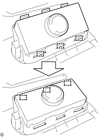
(b) Push in the instrument panel passenger without door airbag assembly to engage the hooks to the instrument panel sub-assembly.
(c) Install the 2 screws.
2. INSTALL NO. 2 INSTRUMENT PANEL WIRE
(a) Connect the airbag connector of the No. 2 instrument panel wire to the instrument panel passenger without door airbag assembly.
NOTICE:
When connecting any airbag connector, take care not to damage the airbag wire harness.
HINT:
Refer to How to Connect or Disconnect Airbag Connector:
Click here

(b) Engage the clamp.
3. INSTALL INSTRUMENT PANEL SUB-ASSEMBLY
Click here

 Removal
REMOVAL CAUTION / NOTICE / HINT The necessary procedures (adjustment, calibration, initialization, or registration) that must be performed after parts are removed, installed, or replaced during the instrument panel passenger without door airbag assembly removal/installation are shown below...

Other information:
Toyota Yaris XP210 (2020-2026) Reapir and Service Manual: Rear Seat Belt Warning Light Malfunction
DESCRIPTION The main body ECU (multiplex network body ECU) detects whether either the rear doors are open or closed based on the courtesy light switch condition and then sends the rear door status signal to the combination meter assembly. The power distribution box assembly detects whether either the rear seat belts are fastened or unfastened based on the rear seat belt buckle switch condition and then sends the rear seat belt buckle switch status signal to the combination meter assembly...
Toyota Yaris XP210 (2020-2026) Reapir and Service Manual: Ambient Light
ComponentsCOMPONENTS ILLUSTRATION *A for Driver Side *B for Front Passenger Side *1 MULTIPLEX NETWORK MASTER SWITCH ASSEMBLY WITH FRONT ARMREST BASE UPPER PANEL *2 POWER WINDOW REGULATOR SWITCH ASSEMBLY WITH FRONT ARMREST BASE UPPER PANEL *3 NO...
Categories
- Manuals Home
- Toyota Yaris Owners Manual
- Toyota Yaris Service Manual
- Engine & Hybrid System
- Brake System Control Module "A" System Voltage System Voltage Low (C137BA2)
- How to connect USB port/Auxiliary jack
- New on site
- Most important about car
Break-In Period
No special break-in is necessary, but a few precautions in the first 600 miles (1,000 km) may add to the performance, economy, and life of the vehicle.
Do not race the engine. Do not maintain one constant speed, either slow or fast, for a long period of time. Do not drive constantly at full-throttle or high engine rpm for extended periods of time. Avoid unnecessary hard stops. Avoid full-throttle starts.