
Toyota Yaris: Inner Rear View Mirror / Installation
INSTALLATION
PROCEDURE
1. INSTALL INNER REAR VIEW MIRROR ASSEMBLY (w/o Pre-collision System)
(a) Install the inner rear view mirror assembly as shown in the illustration.
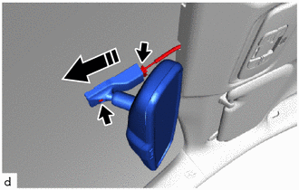
 | Install in this Direction |
(b) Using a T20 ''TORX'' socket wrench, install the screw.
Torque:
1.8 N·m {18 kgf·cm, 16 in·lbf}
(c) Connect the connector.
2. INSTALL INNER REAR VIEW MIRROR ASSEMBLY (w/ Pre-collision System)
(a) Install the inner rear view mirror assembly as shown in the illustration.
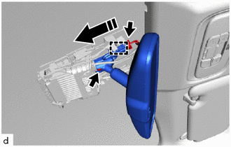
 | Install in this Direction |
(b) Using a T20 ''TORX'' socket wrench, install the screw.
Torque:
1.8 N·m {18 kgf·cm, 16 in·lbf}
(c) Engage the clamp.
(d) Connect the connector.
3. INSTALL INNER REAR VIEW MIRROR STAY HOLDER COVER (w/o Pre-collision System)
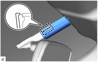
| (a) Engage the claws to install the inner rear view mirror stay holder cover. |
|
(b) Slide the inner rear view mirror stay holder cover to engage the guides as shown in the illustration.
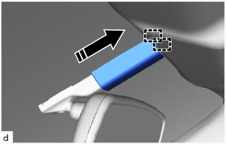
 | Slide in this Direction |
4. INSTALL NO. 1 FORWARD RECOGNITION COVER (w/ Pre-collision System)
Click here

5. INSTALL NO. 2 FORWARD RECOGNITION COVER (w/ Pre-collision System)
Click here

 Removal
REMOVAL PROCEDURE 1. REMOVE INNER REAR VIEW MIRROR STAY HOLDER COVER (w/o Pre-collision System) (a) Slide the inner rear view mirror stay holder cover to disengage the guides as shown in the illustration...

Other information:
Toyota Yaris XP210 (2020-2026) Owner's Manual: To return the seatback to its upright position
4-Door Make sure that the seat belt passes through the seat belt guide correctly and it is not twisted, then raise the seatback while preventing the seat belt from being caught in the seatback. Press the seatback rearward and lock it in place...
Toyota Yaris XP210 (2020-2026) Reapir and Service Manual: Precaution
PRECAUTION CAUTION: Failure to carry out service procedures in the correct sequence could cause SRS parts to unexpectedly deploy and possibly lead to serious injuries. Furthermore, if a mistake is made when servicing SRS parts, they may fail to operate when required...
Categories
- Manuals Home
- Toyota Yaris Owners Manual
- Toyota Yaris Service Manual
- How to connect USB port/Auxiliary jack
- Battery Monitor Module General Electrical Failure (P058A01)
- Power Integration No.1 System Missing Message (B235287,B235587,B235787-B235987)
- New on site
- Most important about car
Liftgate/Trunk Lid
WARNING
Never allow a person to ride in the luggage compartment/trunk
Allowing a person to ride in the luggage compartment/trunk is dangerous. The person in the luggage compartment/trunk could be seriously injured or killed during sudden braking or a collision.
Do not drive with the liftgate/trunk lid open
