Toyota Yaris: Smart Key System (for Start Function) / IG Circuit Short to Ground (B227111)
DESCRIPTION
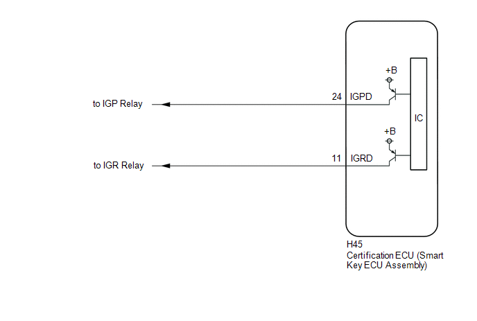
This DTC is stored when a malfunction in the IG circuit or IG hold circuit of the certification ECU (smart key ECU assembly) is detected.
| DTC No. | Detection Item | DTC Detection Condition | Trouble Area | Note |
|---|---|---|---|---|
| B227111 | IG Circuit Short to Ground | When either of the following conditions is met (1-trip detection logic*1):
|
|
|
- *1: Only detected while a malfunction is present and the ignition switch is ON.
- *2: The IG circuit and IG hold circuit activate the IG relay.
- *3: After the IG circuit turns on, even if the certification ECU (smart key ECU assembly) malfunctions, the IG hold circuit will maintain the power source mode in ON.
| Vehicle Condition when Malfunction Detected | Fail-safe Function when Malfunction Detected |
|---|---|
| The ignition switch cannot be turned to ON (the engine cannot be started). | The power source mode cannot be changed to ON. |
| DTC No. | Data List and Active Test |
|---|---|
| B227111 | Power Source Control
|
WIRING DIAGRAM
CAUTION / NOTICE / HINT
NOTICE:
- When using the GTS with the ignition switch off, connect the GTS to the DLC3 and turn a courtesy light switch on and off at intervals of 1.5 seconds or less until communication between the GTS and the vehicle begins. Then select the vehicle type under manual mode and enter the following menus: Body Electrical / Smart Key. While using the GTS, periodically turn a courtesy light switch on and off at intervals of 1.5 seconds or less to maintain communication between the GTS and the vehicle.
-
The smart key system (for Start Function) uses the LIN communication system and CAN communication system. Inspect the communication function by following How to Proceed with Troubleshooting. Troubleshoot the smart key system (for Start Function) after confirming that the communication systems are functioning properly.
Click here

-
Before replacing the certification ECU (smart key ECU assembly), refer to Registration.
Click here

- After repair, confirm that no DTCs are output by performing "DTC Output Confirmation Operation".
PROCEDURE
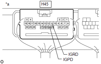
| 1. | CHECK CERTIFICATION ECU (SMART KEY ECU ASSEMBLY) |
| (a) Measure the voltage according to the value(s) in the table below. Standard Voltage:
|
|
| OK |
 | END (TEMPORARY CONNECTION FAILURE IS SUSPECTED) |
| NG |
 | REPLACE CERTIFICATION ECU (SMART KEY ECU ASSEMBLY) |

 ACC Circuit Short to Ground (B227411)
DESCRIPTION This DTC is stored when a malfunction in the ACC output circuit is detected. The ACC output circuit is the circuit between terminal ACCD of the certification ECU (smart key ECU assembly) and the ACC relay...
Other information:
Toyota Yaris XP210 (2020-2026) Reapir and Service Manual: VIN Not Programmed (P063051)
MONITOR DESCRIPTION DTC P063051 is stored when the Vehicle Identification Number (VIN) is not stored in the ECM or the stored VIN is not accurate. DTC No. Detection Item DTC Detection Condition Trouble Area MIL Note P063051 VIN Not Programmed Either of the following conditions is met (1 trip detection logic): The VIN is not stored in the ECM...
Toyota Yaris XP210 (2020-2026) Reapir and Service Manual: Components
COMPONENTS ILLUSTRATION *1 NO. 1 INSTRUMENT PANEL UNDER COVER SUB-ASSEMBLY *2 CLUTCH PEDAL STROKE SENSOR ASSEMBLY *3 BRAKE PEDAL RETURN SPRING - - Tightening torque for "Major areas involving basic vehicle performance such as moving/turning/stopping": N*m (kgf*cm, ft...
Categories
- Manuals Home
- Toyota Yaris Owners Manual
- Toyota Yaris Service Manual
- Headlights
- Immobilizer System
- How to use USB mode
- New on site
- Most important about car
Key Suspend Function
If a key is left in the vehicle, the functions of the key left in the vehicle are temporarily suspended to prevent theft of the vehicle.
To restore the functions, press the unlock button on the functions-suspended key in the vehicle.