Toyota Yaris: Stop And Start System / External BBC Circuit (P33B300)
DESCRIPTION
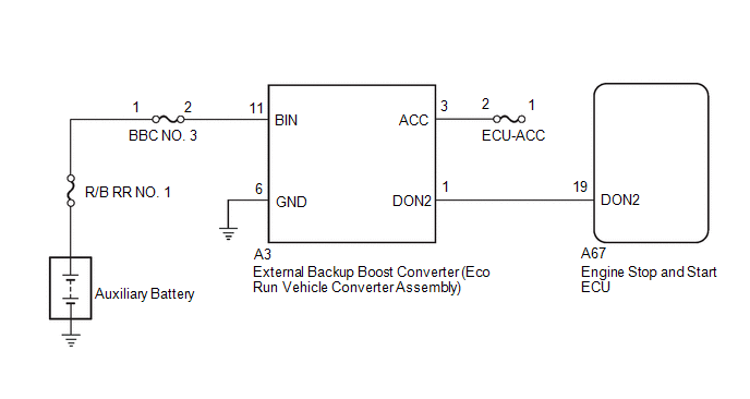
When the engine is started (high electrical load) from engine stopped by the stop and start control, the external backup boost converter (eco run vehicle converter assembly) supplements auxiliary battery voltage in order to prevent the function from being disabled due to decrease in power source voltage supplied to the navigation system.
Актуальная информация Брусчатка тротуарная Воронеж тут.After receiving a request from the engine stop and start ECU, the external backup boost converter (eco run vehicle converter assembly) helps maintain the power source voltage if the auxiliary battery voltage drops due to the high electrical load when the engine is restarted by stop and start control. The DON2 terminal of the external backup boost converter (eco run vehicle converter assembly) receives power supply voltage supplement requests from the engine stop and start ECU and switches from idle mode to supplement mode.
When the engine is started by the stop and start control, if the external backup boost converter (eco run vehicle converter assembly) does not maintain the specified voltage, an error is sent to the engine stop and start ECU. Then, the engine stop and start ECU stores DTC P33B300, and the stop and start cancel indicator blinks.
| DTC No. | Detection Item | DTC Detection Condition | Trouble Area | Warning Indicate | Memory | Note |
|---|---|---|---|---|---|---|
| P33B300 | External BBC Circuit | Any of the following conditions are met for 1 second or more (1 trip detection logic):
|
| Blinks | DTC stored | SAE Code: P33B3 |
CONFIRMATION DRIVING PATTERN
CONFIRMATION AFTER TROUBLESHOOTING
HINT:
-
If the cable is disconnected from the auxiliary battery terminal, stop and start control is prohibited until refresh charge is completed.
In this case, let the vehicle idle to complete the refresh charge. The refresh charge is complete when the Data List item "Status of Auxiliary Battery Charge Control" changes from "Refresh Charge Mode". (Usually, idling the engine for 5 to 60 minutes with the auxiliary battery fluid temperature at 11°C (51°F) or higher, the refresh charge will be completed.)
-
If the GTS is not available and the Data List item "Status of Auxiliary Battery Charge Control" cannot be checked, charge the auxiliary battery by idling the engine for approximately 5 to 60 minutes or driving the vehicle, and then drive the vehicle and check that stop and start control operates.
If the engine is started with the hood open, the system determines that a jump start has occurred. Therefore, make sure that the hood is closed before starting the engine and driving the vehicle.
- After the refresh charge completes, turn the ignition switch off, wait for at least 30 seconds, and then start the engine again. If the vehicle enters refresh charge mode again while the engine is idling, the initial refresh charge did not properly complete, so wait for the refresh charge to complete.
- Allow the engine to idle for 3 minutes after it is warmed up and check that the engine idle speed is within 50 rpm of the target idle speed.
(a) Clear the DTCs.
Powertrain > Stop and Start > Clear DTCs(b) Start the engine and warm it up.
(c) Drive the vehicle at 7 km/h (4 mph) or more.
CAUTION:
When performing Confirmation Driving Pattern, obey all speed limits and traffic laws.
(d) Depress the brake pedal and stop the vehicle.
(e) Keep the engine stopped by stop and start control for 1 second or more. (Keep the shift lever in D.)
(f) Release the brake pedal with the shift lever in D to start the engine.
HINT:
If the engine cranks slowly when the engine is restarted, it can be determined that the auxiliary battery voltage is low.
(g) Check that DTCs are not output.
Powertrain > Stop and Start > Trouble CodesSTOP AND START SYSTEM OPERATION CHECK
Click here

WIRING DIAGRAM
CAUTION / NOTICE / HINT
NOTICE:
Inspect the fuses for circuits related to this system before performing the following procedure.
HINT:
-
Using the GTS, read the freeze frame data before troubleshooting. System condition information is recorded as freeze frame data the moment a DTC is stored. This information can be useful when troubleshooting.
Click here

-
For wire harness and connector inspection procedures and precautions, refer to "
 "
"
-
DTCs for the stop and start system are not cleared even if the malfunction has been repaired. After repairing the malfunction, be sure to clear the DTCs.
Click here

PROCEDURE
| 1. | CONFIRM FREEZE FRAME DATA (STATE OF EXTERNAL BBC) |
NOTICE:
Clearing the DTC will also clear the freeze frame data, so before clearing be sure to record the freeze frame data.
(a) Following the display on the GTS, check the freeze frame data and read "State of External BBC" in the freeze frame data when P33B300 was output.
Powertrain > Stop and Start| Tester Display |
|---|
| State of External BBC |
| GTS Display | Proceed to |
|---|---|
| Duty Err | A |
| Cycle Err | B |
| Low Vol | C |
| Overvoltage | D |
| A |
 | REPLACE EXTERNAL BACKUP BOOST CONVERTER (ECO RUN VEHICLE CONVERTER ASSEMBLY) |
| B |
 | REPLACE EXTERNAL BACKUP BOOST CONVERTER (ECO RUN VEHICLE CONVERTER ASSEMBLY) |
| D |
 | GO TO STEP 4 |
|

| 2. | CHECK CONNECTOR (EXTERNAL BACKUP BOOST CONVERTER (ECO RUN VEHICLE CONVERTER ASSEMBLY)) |
(a) Check if the connector of the A3 external backup boost converter (eco run vehicle converter assembly) is connected securely.
OK:
The connector is securely connected.
| NG |
 | CONNECT CONNECTOR CORRECTLY |
|

| 3. | CHECK HARNESS AND CONNECTOR (EXTERNAL BACKUP BOOST CONVERTER (ECO RUN VEHICLE CONVERTER ASSEMBLY) POWER SOURCE CIRCUIT) |
(a) Disconnect the A3 external backup boost converter (eco run vehicle converter assembly) connector.
(b) Measure the voltage according to the value(s) in the table below.
Standard Voltage:
| Tester Connection | Condition | Specified Condition |
|---|---|---|
| A3-11 (BIN) - Body ground | Always | 9.5 to 14 V |
| A3-3 (ACC) - Body ground | Ignition switch (ACC) | 9.5 to 14 V |
| NG |
 | REPAIR OR REPLACE HARNESS OR CONNECTOR |
|

| 4. | CHECK HARNESS AND CONNECTOR (ENGINE STOP AND START ECU - EXTERNAL BACKUP BOOST CONVERTER (ECO RUN VEHICLE CONVERTER ASSEMBLY)) |
(a) Disconnect the A67 engine stop and start ECU connector.
(b) Disconnect the A3 external backup boost converter (eco run vehicle converter assembly) connector.
(c) Measure the resistance according to the value(s) in the table below.
Standard Resistance:
| Tester Connection | Condition | Specified Condition |
|---|---|---|
| A67-19 (DON2) - A3-1 (DON2) | Always | Below 1 Ω |
| A67-19 (DON2) - Body ground and other terminals | Always | 10 kΩ or higher |
| A3-1 (DON2) - Body ground and other terminals | Always | 10 kΩ or higher |
| NG |
 | REPAIR OR REPLACE HARNESS OR CONNECTOR |
|

| 5. | CHECK HARNESS AND CONNECTOR (BBC NO. 3 FUSE, ECU-ACC FUSE - EXTERNAL BACKUP BOOST CONVERTER (ECO RUN VEHICLE CONVERTER ASSEMBLY)) |
(a) Disconnect the A3 external backup boost converter (eco run vehicle converter assembly) connector.
(b) Remove the BBC NO. 3 fuse from the No. 3 engine room relay block.
(c) Remove the ECU-ACC fuse from the power distribution box assembly.
(d) Measure the resistance according to the value(s) in the table below.
Standard Resistance:
| Tester Connection | Condition | Specified Condition |
|---|---|---|
| A3-11 (BIN) - BBC NO. 3 fuse terminal 2 | Always | Below 1 Ω |
| A3-3 (ACC) - ECU-ACC fuse terminal 2 | Always | Below 1 Ω |
| A3-11 (BIN) - Body ground and other terminals | Always | 10 kΩ or higher |
| BBC NO. 3 fuse terminal 2 - Body ground and other terminals | Always | 10 kΩ or higher |
| A3-3 (ACC) - Body ground and other terminals | Always | 10 kΩ or higher |
| ECU-ACC fuse terminal 2 - Body ground and other terminals | Always | 10 kΩ or higher |
| OK |
 | REPLACE EXTERNAL BACKUP BOOST CONVERTER (ECO RUN VEHICLE CONVERTER ASSEMBLY) |
| NG |
 | REPAIR OR REPLACE HARNESS OR CONNECTOR |
 Backup Boost Converter "A" Circuit Current Above Threshold (P323A19)
DESCRIPTION A backup boost converter is built into the engine stop and start ECU. The backup boost converter helps maintain auxiliary battery voltage to prevent various functions from failing if power source voltage supplied from the backup boost converter drops due to the high electrical load when the engine is restarted by stop and start control...
 Lost Communication with ECM/PCM "A" Missing Message (U010087,U012687,U012987,U013187,U014087,U015187,U015587,U016487,U117087)
DESCRIPTION The engine stop and start ECU communicates with the SFI system, electronically controlled brake system, power steering system, air conditioning system, airbag system and main body ECU (multiplex network body ECU) via CAN communication...
Other information:
Toyota Yaris XP210 (2020-2026) Reapir and Service Manual: Turbocharger Noise
DESCRIPTION HINT: Turbocharger noise is classified into two types. These are whistling sound and chattering sound. During troubleshooting, first determine the type of noise. Type of Abnormal Noise Outline of Abnormal Noise Major Trouble Area Whistling sound (airflow sound) The whistling sound volume and pitch are proportional to the turbocharger or engine speed...
Toyota Yaris XP210 (2020-2026) Reapir and Service Manual: Failure to Restart from IG-ON Engine Stall
DESCRIPTION This is the troubleshooting procedure for situations where the engine does not restart when attempting to restart it after either a failed engine start occurred under stop and start system control, or a mis-operation during vehicle takeoff resulted in an engine stall...
Categories
- Manuals Home
- Toyota Yaris Owners Manual
- Toyota Yaris Service Manual
- Brake System Control Module "A" System Voltage System Voltage Low (C137BA2)
- Opening and Closing the Liftgate/Trunk Lid
- G16e-gts (engine Mechanical)
- New on site
- Most important about car
Key Suspend Function
If a key is left in the vehicle, the functions of the key left in the vehicle are temporarily suspended to prevent theft of the vehicle.
To restore the functions, press the unlock button on the functions-suspended key in the vehicle.