Toyota Yaris: Stop And Start System / Backup Boost Converter "A" Circuit Current Above Threshold (P323A19)
DESCRIPTION
A backup boost converter is built into the engine stop and start ECU.
The backup boost converter helps maintain auxiliary battery voltage to prevent various functions from failing if power source voltage supplied from the backup boost converter drops due to the high electrical load when the engine is restarted by stop and start control.
The backup boost converter helps maintain the power source voltage if the auxiliary battery voltage drops due to the high electrical load when the engine is restarted by stop and start control.
HINT:
A relay function and fuse function are provided in the backup boost converter.
If there is a malfunction in any of the electrical system circuits connected to the backup boost converter, the fuse and relay functions shut off the malfunctioning circuit to protect other circuits (remains shut off until next trip).
When the electrical system circuit is shut off, power to the circuit is cut off, causing any systems connected to the circuit to be disabled.
The fuse function is reset* when the ignition switch is turned off. If the malfunction still exists in the electrical system circuit that has been shut off by the relay function, it will be shut off again by the relay and fuse functions the next time the ignition switch is turned to ON.
*: A semiconductor fuse self resets according to electric signal.
- Meter / gauge system
- Power steering system
- Headup display system
- Toyota Safety Sense
- Air conditioning system
- Electronically controlled brake system
| DTC No. | Detection Item | DTC Detection Condition | Trouble Area | Warning Indicate | Memory | Note |
|---|---|---|---|---|---|---|
| P323A19 | Backup Boost Converter "A" Circuit Current Above Threshold | The following condition continues for 1 second or more (1 trip detection logic):
|
| Blinks | DTC stored | SAE Code: P323A |
- *1: w/ Headup Display
- *2: w/ Toyota Safety Sense
CONFIRMATION DRIVING PATTERN
CONFIRMATION AFTER TROUBLESHOOTING
HINT:
-
If the cable is disconnected from the auxiliary battery terminal, stop and start control is prohibited until refresh charge is completed.
In this case, let the vehicle idle to complete the refresh charge. The refresh charge is complete when the Data List item Status of Auxiliary Battery Charge Control changes from "Refresh Charge Mode". (Usually, idling the engine for 5 to 60 minutes with the auxiliary battery fluid temperature at 11°C (52°F) or higher, the refresh charge will be completed.)
-
If the GTS is not available and the Data List item Status of Auxiliary Battery Charge Control cannot be checked, charge the auxiliary battery by idling the engine for approximately 5 to 60 minutes or driving the vehicle, and then drive the vehicle and check that stop and start control operates.
If the engine is started with the hood open, the system determines that a jump start has occurred. Therefore, make sure that the hood is closed before starting the engine and driving the vehicle.
- After the refresh charge completes, turn the ignition switch off, wait for at least 30 seconds, and then start the engine again. If the vehicle enters refresh charge mode again while the engine is idling, the initial refresh charge did not properly complete, so wait for the refresh charge to complete.
- Allow the engine to idle for 3 minutes after it is warmed up and check that the engine idle speed is within 50 rpm of the target idle speed.
(a) Clear the DTCs.
Powertrain > Stop and Start > Clear DTCs(b) Start the engine and warm it up.
(c) Drive the vehicle at 7 km/h (4 mph) or more.
CAUTION:
When performing Confirmation Driving Pattern, obey all speed limits and traffic laws.
(d) Depress the brake pedal and stop the vehicle.
(e) Keep the engine stopped by stop and start control for 1 second or more. (Keep the shift lever in D.)
(f) Release the brake pedal with the shift lever in D to start the engine.
HINT:
If the engine cranks slowly when the engine is restarted, it can be determined that the auxiliary battery voltage is low.
(g) Check that DTCs are not output.
Powertrain > Stop and Start > Trouble CodesSTOP AND START SYSTEM OPERATION CHECK
HINT:
-
If the cable is disconnected from the auxiliary battery terminal, stop and start control is prohibited until refresh charge is completed.
In this case, let the vehicle idle to complete the refresh charge. The refresh charge is complete when the Data List item Status of Auxiliary Battery Charge Control changes from "Refresh Charge Mode". (Usually, idling the engine for 5 to 60 minutes with the auxiliary battery fluid temperature at 11°C (52°F) or higher, the refresh charge will be completed.)
-
If the GTS is not available and the Data List item Status of Auxiliary Battery Charge Control cannot be checked, charge the auxiliary battery by idling the engine for approximately 5 to 60 minutes or driving the vehicle, and then drive the vehicle and check that stop and start control operates.
If the engine is started with the hood open, the system determines that a jump start has occurred. Therefore, make sure that the hood is closed before starting the engine and driving the vehicle.
- After the refresh charge completes, turn the ignition switch off, wait for at least 30 seconds, and then start the engine again. If the vehicle enters refresh charge mode again while the engine is idling, the initial refresh charge did not properly complete, so wait for the refresh charge to complete.
(a) Start the engine and warm it up.
(b) Turn the air conditioning system off.
(c) Drive the vehicle at 7 km/h (4 mph) or more.
CAUTION:
When performing Confirmation Driving Pattern, obey all speed limits and traffic laws.
(d) Stop the vehicle, move the shift lever to neutral and release the clutch pedal.
(e) Allow the engine to stop by stop and start control.
(f) Depress the clutch pedal and start the engine.
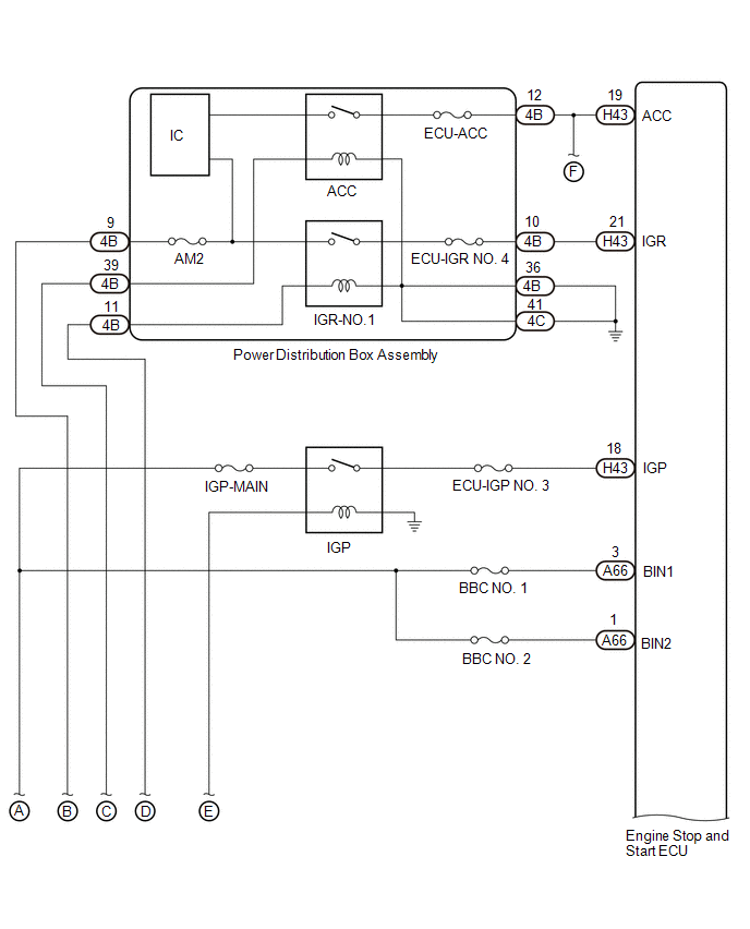
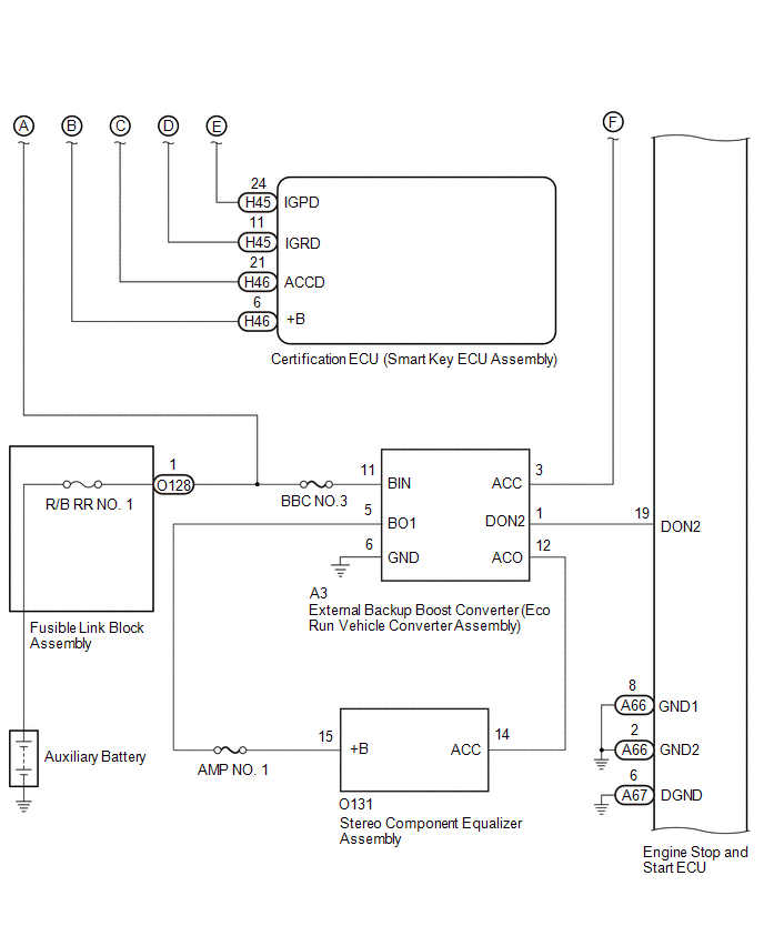
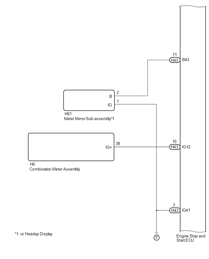
WIRING DIAGRAM
CAUTION / NOTICE / HINT
NOTICE:
-
Before replacing the engine stop and start ECU, read the number of starter operations and write it into a new engine stop and start ECU.
Click here

-
After replacing the engine stop and start ECU, perform learning of the external backup boost converter (eco run vehicle converter assembly).
Click here

-
After replacing the engine stop and start ECU or air conditioning amplifier assembly, reset and perform learning of the air conditioning information in the engine stop and start ECU.
Click here

- Inspect the fuses for circuits related to this system before performing the following procedure.
HINT:
-
Using the GTS, read the freeze frame data before troubleshooting. System condition information is recorded as freeze frame data the moment a DTC is stored. This information can be useful when troubleshooting.
Click here

-
If electrical load from additional devices installed to the vehicle (aftermarket audio system, etc.) is applied to the B43, IG12, IG31 or IG41 terminal in the engine stop and start ECU, the fuse function of the backup boost converter may operate.
If the fuse function of the backup boost converter operates, any systems connected to the B43, IG12, IG31 or IG41 terminal in the engine stop and start ECU will not operate.
-
For wire harness and connector inspection procedures and precautions, refer to "
 "
"
-
DTCs for the stop and start system are not cleared even if the malfunction has been repaired. After repairing the malfunction, be sure to clear the DTCs.
Click here

PROCEDURE
| 1. | CHECK HARNESS AND CONNECTOR (ENGINE STOP AND START ECU - BBC NO. 1 FUSE AND BBC NO. 2 FUSE) |
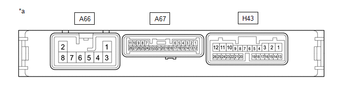
(a) Disconnect the A66 engine stop and start ECU connector.
(b) Remove the BBC NO. 1 fuse and BBC NO. 2 fuse from the No. 1 engine room relay block.
(c) Measure the resistance according to the value(s) in the table below.
Standard Resistance:
| Tester Connection | Condition | Specified Condition |
|---|---|---|
| A66-1 (BIN2) - 2 (BBC NO. 2 fuse holder) | Always | Below 1 Ω |
| A66-3 (BIN1) - 2 (BBC NO. 1 fuse holder) | Always | Below 1 Ω |
| A66-1 (BIN2) - Body ground and other terminals | Always | 10 kΩ or higher |
| 2 (BBC NO. 2 fuse holder) - Body ground and other terminals | Always | 10 kΩ or higher |
| A66-3 (BIN1) - Body ground and other terminals | Always | 10 kΩ or higher |
| 2 (BBC NO. 1 fuse holder) - Body ground and other terminals | Always | 10 kΩ or higher |
| NG |
 | REPAIR OR REPLACE HARNESS OR CONNECTOR |
|

| 2. | CHECK HARNESS AND CONNECTOR (ENGINE STOP AND START ECU - EACH ECU OR SENSOR) |
(a) Disconnect the H43 engine stop and start ECU connector.
(b) Disconnect the H6 combination meter assembly connector.
(c) Disconnect the H31 air conditioning control assembly connector.
(d) Disconnect the H1 power steering ECU assembly connector.
(e) Disconnect the A108 skid control ECU (brake actuator assembly) connector.
(f) Measure the resistance according to the value(s) in the table below.
Click here

Standard Resistance:
| Tester Connection | Condition | Specified Condition |
|---|---|---|
| H43-10 (IG12) - H6-38 (IG+) | Always | Below 1 Ω |
| H43-3 (IG41) - H31-9 (IG+) | Always | Below 1 Ω |
| H43-23 (IG31) - H1-1 (IG) | Always | Below 1 Ω |
| H43-23 (IG31) - A108-12 (IGR) | Always | Below 1 Ω |
| H43-10 (IG12) - Body ground and other terminals | Always | 10 kΩ or higher |
| H43-23 (IG31) - Body ground and other terminals | Always | 10 kΩ or higher |
| H43-3 (IG41) - Body ground and other terminals | Always | 10 kΩ or higher |
| NG |
 | REPAIR OR REPLACE HARNESS OR CONNECTOR |
|

| 3. | CHECK VEHICLE SPECIFICATION |
(a) Check the vehicle specification
| Result | Proceed to |
|---|---|
| w/ Headup Display | A |
| w/o Headup Display | B |
| B |
 | GO TO STEP 11 |
|

| 4. | CHECK HARNESS AND CONNECTOR (ENGINE STOP AND START ECU - EACH ECU OR SENSOR) |
(a) Disconnect the H43 engine stop and start ECU connector.
(b) Disconnect the H61 meter mirror sub-assembly connector.
(c) Measure the resistance according to the value(s) in the table below.
Click here

Standard Resistance:
| Tester Connection | Condition | Specified Condition |
|---|---|---|
| H43-11 (B43) - H61-2(B) | Always | Below 1 Ω |
| H43-11 (B43) - Body ground and other terminals | Always | 10 kΩ or higher |
| NG |
 | REPAIR OR REPLACE HARNESS OR CONNECTOR |
|

| 5. | CHECK VEHICLE SPECIFICATION |
(a) Check the vehicle specification
| Result | Proceed to |
|---|---|
| w/ Toyota Safety Sense | A |
| w/o Toyota Safety Sense | B |
| B |
 | GO TO STEP 9 |
|

| 6. | CHECK HARNESS AND CONNECTOR (ENGINE STOP AND START ECU - EACH ECU OR SENSOR) |
(a) Disconnect the H43 engine stop and start ECU connector.
(b) Disconnect the B8 millimeter wave radar sensor assembly connector.
(c) Measure the resistance according to the value(s) in the table below.
Click here

Standard Resistance:
| Tester Connection | Condition | Specified Condition |
|---|---|---|
| H43-3 (IG41) - B8-8 (IGB) | Always | Below 1 Ω |
| H43-3 (IG41) - Body ground and other terminals | Always | 10 kΩ or higher |
| NG |
 | REPAIR OR REPLACE HARNESS OR CONNECTOR |
|

| 7. | CHECK ENGINE STOP AND START ECU |

| *a | Component without harness connected (Engine Stop and Start ECU) | - | - |
(a) Disconnect the A66, A67 and H43 engine stop and start ECU connectors.
(b) Measure the resistance according to the value(s) in the table below.
Click here

Standard Resistance:
| Tester Connection | Condition | Specified Condition |
|---|---|---|
| H43-12 (B42) - A67-6 (DGND) | Always | 10 kΩ or higher |
| H43-11 (B43) - A67-6 (DGND) | Always | 10 kΩ or higher |
| H43-3 (IG41) - A67-6 (DGND) | Always | 10 kΩ or higher |
| NG |
 | REPLACE ENGINE STOP AND START ECU |
|

| 8. | CHECK VEHICLE CONDITION (B43 OR IG41 CIRCUIT) |
(a) Check that additional devices installed to the vehicle (aftermarket audio system, etc.) are not connected to the B43 or IG41 terminal circuit of the engine stop and start ECU.
| Result | Proceed to |
|---|---|
| Load from an additional device installed to the vehicle (aftermarket audio system, etc.) is not applied. | A |
| Load from an additional device installed to the vehicle (aftermarket audio system, etc.) is applied. | B |
| A |
 | TROUBLESHOOT ECUS CONNECTED TO TERMINALS B43 AND IG41 |
| B |
 | END (REMOVE ADDITIONAL DEVICE) |
| 9. | CHECK ENGINE STOP AND START ECU |

| *a | Component without harness connected (Engine Stop and Start ECU) | - | - |
(a) Disconnect the A66, A67 and H43 engine stop and start ECU connectors.
(b) Measure the resistance according to the value(s) in the table below.
Click here

Standard Resistance:
| Tester Connection | Condition | Specified Condition |
|---|---|---|
| H43-12 (B42) - A67-6 (DGND) | Always | 10 kΩ or higher |
| H43-11 (B43) - A67-6 (DGND) | Always | 10 kΩ or higher |
| H43-3 (IG41) - A67-6 (DGND) | Always | 10 kΩ or higher |
| NG |
 | REPLACE ENGINE STOP AND START ECU |
|

| 10. | CHECK VEHICLE CONDITION (B43 OR IG41 CIRCUIT) |
(a) Check that additional devices installed to the vehicle (aftermarket audio system, etc.) are not connected to the B43 or IG41 terminal circuit of the engine stop and start ECU.
| Result | Proceed to |
|---|---|
| Load from an additional device installed to the vehicle (aftermarket audio system, etc.) is not applied. | A |
| Load from an additional device installed to the vehicle (aftermarket audio system, etc.) is applied. | B |
| A |
 | TROUBLESHOOT ECUS CONNECTED TO TERMINALS B43 AND IG41 |
| B |
 | END (REMOVE ADDITIONAL DEVICE) |
| 11. | CHECK VEHICLE SPECIFICATION |
(a) Check the vehicle specification
| Result | Proceed to |
|---|---|
| w/ Toyota Safety Sense | A |
| w/o Toyota Safety Sense | B |
| B |
 | GO TO STEP 15 |
|

| 12. | CHECK HARNESS AND CONNECTOR (ENGINE STOP AND START ECU - EACH ECU OR SENSOR) |
(a) Disconnect the H43 engine stop and start ECU connector.
(b) Disconnect the B8 millimeter wave radar sensor assembly connector.
(c) Measure the resistance according to the value(s) in the table below.
Click here

Standard Resistance:
| Tester Connection | Condition | Specified Condition |
|---|---|---|
| H43-3 (IG41) - B8-8 (IGB) | Always | Below 1 Ω |
| H43-3 (IG41) - Body ground and other terminals | Always | 10 kΩ or higher |
| NG |
 | REPAIR OR REPLACE HARNESS OR CONNECTOR |
|

| 13. | CHECK ENGINE STOP AND START ECU |

| *a | Component without harness connected (Engine Stop and Start ECU) | - | - |
(a) Disconnect the A66, A67 and H43 engine stop and start ECU connectors.
(b) Measure the resistance according to the value(s) in the table below.
Click here

Standard Resistance:
| Tester Connection | Condition | Specified Condition |
|---|---|---|
| H43-12 (B42) - A67-6 (DGND) | Always | 10 kΩ or higher |
| H43-11 (B43) - A67-6 (DGND) | Always | 10 kΩ or higher |
| H43-3 (IG41) - A67-6 (DGND) | Always | 10 kΩ or higher |
| NG |
 | REPLACE ENGINE STOP AND START ECU |
|

| 14. | CHECK VEHICLE CONDITION (B43 OR IG41 CIRCUIT) |
(a) Check that additional devices installed to the vehicle (aftermarket audio system, etc.) are not connected to the B43 or IG41 terminal circuit of the engine stop and start ECU.
| Result | Proceed to |
|---|---|
| Load from an additional device installed to the vehicle (aftermarket audio system, etc.) is not applied. | A |
| Load from an additional device installed to the vehicle (aftermarket audio system, etc.) is applied. | B |
| A |
 | TROUBLESHOOT ECUS CONNECTED TO TERMINALS B43 AND IG41 |
| B |
 | END (REMOVE ADDITIONAL DEVICE) |
| 15. | CHECK ENGINE STOP AND START ECU |
| *a | Component without harness connected (Engine Stop and Start ECU) | - | - |
(a) Disconnect the A66, A67 and H43 engine stop and start ECU connectors.
(b) Measure the resistance according to the value(s) in the table below.
Click here

Standard Resistance:
| Tester Connection | Condition | Specified Condition |
|---|---|---|
| H43-12 (B42) - A67-6 (DGND) | Always | 10 kΩ or higher |
| H43-11 (B43) - A67-6 (DGND) | Always | 10 kΩ or higher |
| H43-3 (IG41) - A67-6 (DGND) | Always | 10 kΩ or higher |
| NG |
 | REPLACE ENGINE STOP AND START ECU |
|

| 16. | CHECK VEHICLE CONDITION (B43 OR IG41 CIRCUIT) |
(a) Check that additional devices installed to the vehicle (aftermarket audio system, etc.) are not connected to the B43 or IG41 terminal circuit of the engine stop and start ECU.
| Result | Proceed to |
|---|---|
| Load from an additional device installed to the vehicle (aftermarket audio system, etc.) is not applied. | A |
| Load from an additional device installed to the vehicle (aftermarket audio system, etc.) is applied. | B |
| A |
 | TROUBLESHOOT ECUS CONNECTED TO TERMINALS B43 AND IG41 |
| B |
 | END (REMOVE ADDITIONAL DEVICE) |
 Backup Boost Converter Circuit Board(Thermistor) Signal Compare Failure (P30DF62,P30EF4B,P323A00,P323A16,P323AA2,P323B29,P323B38)
DESCRIPTION Refer to DTC P323A19. Click here
DTC No. Detection Item DTC Detection Condition Trouble Area Warning Indicate Memory Note P30DF62 Backup Boost Converter Circuit Board(Thermistor) Signal Compare Failure The following conditions is met for 1 second or more (1 trip detection logic):
Difference in temperature between thermistor 1 and thermistor 2 of the engine stop and start ECU is 40°C (72°F) or higher...
 External BBC Circuit (P33B300)
DESCRIPTION When the engine is started (high electrical load) from engine stopped by the stop and start control, the external backup boost converter (eco run vehicle converter assembly) supplements auxiliary battery voltage in order to prevent the function from being disabled due to decrease in power source voltage supplied to the navigation system...
Other information:
Toyota Yaris XP210 (2020-2026) Reapir and Service Manual: Removal
REMOVAL CAUTION / NOTICE / HINT The necessary procedures (adjustment, calibration, initialization, or registration) that must be performed after parts are removed and installed, or replaced during the rear differential carrier assembly removal/installation are shown below...
Toyota Yaris XP210 (2020-2026) Reapir and Service Manual: Installation
INSTALLATION CAUTION / NOTICE / HINT NOTICE: This procedure includes the installation of small-head bolts. Refer to Small-Head Bolts of Basic Repair Hint to identify the small-head bolts. Click here PROCEDURE 1. TEMPORARILY INSTALL FUEL PUMP ASSEMBLY NOTICE: When replacing the fuel pump assembly, it is necessary to replace the No...
Categories
- Manuals Home
- Toyota Yaris Owners Manual
- Toyota Yaris Service Manual
- Engine & Hybrid System
- Brake System Control Module "A" System Voltage System Voltage Low (C137BA2)
- How to connect USB port/Auxiliary jack
- New on site
- Most important about car
Refueling
Before refueling, close all the doors, windows, and the liftgate/trunk lid, and switch the ignition OFF.
To open the fuel-filler lid, pull the remote fuel-filler lid release.
