
Toyota Yaris: Audio / Video / Digital Audio Broadcasting Antenna
Components
COMPONENTS
ILLUSTRATION
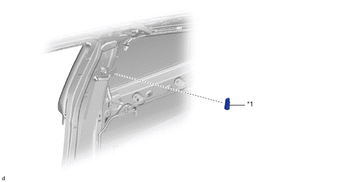
| https://spinbetcasino.info/en-nz/ *1 | DIGITAL AUDIO BROADCASTING ANTENNA BASE | - | - |
Removal
REMOVAL
CAUTION / NOTICE / HINT
HINT:
When the cable is disconnected / reconnected to the auxiliary battery terminal, systems temporarily stop operating. However, each system has a function that completes learning the first time the system is used.
-
Learning completes when vehicle is driven
Effect/Inoperative Function When Necessary Procedures are not Performed
Necessary Procedures
Link
Lane tracing assist system
Drive the vehicle straight ahead at 35 km/h (22 mph) or more for 5 second or more.

Pre-collision system
Stop and start system
Drive the vehicle until stop and start control is permitted (approximately 5 to 60 minutes)

-
Learning completes when vehicle is operated normally
Effect/Inoperative Function When Necessary Procedures are not Performed
Necessary Procedures
Link
Power door lock control system
- Back door opener
Perform door unlock operation with door control switch or electrical key transmitter sub-assembly switch.

Air conditioning system
After the ignition switch is turned to ON, the servo motor standard position is recognized.
-
PROCEDURE
1. REMOVE CENTER PILLAR UPPER GARNISH
Click here

2. REMOVE DIGITAL AUDIO BROADCASTING ANTENNA BASE
NOTICE:
Do not touch the contact points.
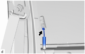
| (a) Disconnect the connector. |
|
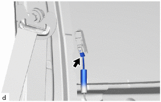
(b) Disengage the claw to remove the digital audio broadcasting antenna base as shown in the illustration.
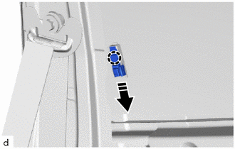
 | Remove in this Direction |
Installation
INSTALLATION
PROCEDURE
1. INSTALL CENTER PILLAR UPPER GARNISH
NOTICE:
Do not touch the contact points.
(a) Engage the claw to install the digital audio broadcasting antenna base as shown in the illustration.
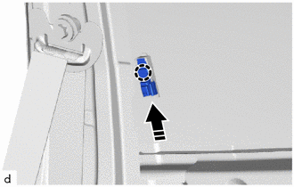
 | Install in this Direction |
| (b) Connect the connector. |
|
2. INSTALL QUARTER TRIM PANEL ASSEMBLY
Click here

 Lost Communication With ECM/PCM "A" Missing Message (U010087,U012987,U014087)
DESCRIPTION These DTCs are stored when a malfunction occurs in the CAN communication circuit. DTC No. Detection Item DTC Detection Condition Trouble Area U010087 Lost Communication With ECM/PCM "A" Missing Message When the stereo component equalizer assembly detects a CAN communication malfunction in the engine system for 1 second or more continuously 3 seconds after the ignition switch is turned to ON* CAN communication system U012987 Lost Communication With Brake System Control Module Missing Message When the stereo component equalizer assembly detects a CAN communication malfunction in the brake system for 1 second or more continuously 3 seconds after the ignition switch is turned to ON* CAN communication system U014087 Lost Communication with Body Control Module Missing Message When the stereo component equalizer assembly detects a CAN communication malfunction in the main body ECU for 3 seconds or more continuously 3 seconds after the ignition switch is turned to ON* CAN communication system HINT: *: Malfunction monitoring is not performed under the following conditions, in order to prevent erroneous detection...

Other information:
Toyota Yaris XP210 (2020-2026) Reapir and Service Manual: System Description
SYSTEM DESCRIPTION LOAD OPERATION OUTPUT (a) Load is turned on or off according to the operation signals and switch signals from each ECU. Components Semiconductor Power Integration ECU Power Distribution Box Assembly Operation Signal Communication Support *1: w/ Front Seat Heater *2: Built into power distribution box assembly Headlight ECU Assembly ○ - Not supported Fog Light Assembly ○ - Supported Rear Window Defogger / Mirror Heater - ○ Supported Taillight - ○ Supported Rear Fog Light - ○ Supported Back-up Light - ○ Not supported Outer Rear View Mirror Assembly - ○ Supported Panel Illumination - ○ Supported Seat Heater LH*1 High/Low - ○ Not supported Seat Heater RH*1 High/Low - ○ Not supported Passenger Seat Buckle Switch Delegated Input - ○ - Occupant Detection Sensor Delegated Input - ○ - Rear Seat RH Buckle Switch Delegated Input - ○ - Rear Seat CTR Buckle Switch Delegated Input - ○ - Rear Seat LH Buckle Switch Delegated Input - ○ - IGR Relay*2 - ○ Not supported SEMICONDUCTOR FUSE FUNCTION (a) When a malfunction current occurs during load operation, the current is shut off before the electrical lines emit smoke, and then load is turned off...
Toyota Yaris XP210 (2020-2026) Reapir and Service Manual: Disassembly
DISASSEMBLY PROCEDURE 1. REMOVE ACTIVE NOISE CONTROL MICROPHONE (w/ Active Noise Control System) Click here 2. REMOVE ROOF HEADLINING HOLDER COVER (w/ Active Noise Control System) HINT: Use the same procedure for the opposite side. (a) Disengage the claws to remove the roof headlining holder cover...
Categories
- Manuals Home
- Toyota Yaris Owners Manual
- Toyota Yaris Service Manual
- Engine & Hybrid System
- Fuel Gauge
- Battery Monitor Module General Electrical Failure (P058A01)
- New on site
- Most important about car
Fuel-Filler Lid and Cap
WARNING
When removing the fuel-filler cap, loosen the cap slightly and wait for any hissing to stop, then remove it
Fuel spray is dangerous. Fuel can burn skin and eyes and cause illness if ingested. Fuel spray is released when there is pressure in the fuel tank and the fuel-filler cap is removed too quickly.
