Toyota Yaris: Front Shock Absorber / Components
COMPONENTS
ILLUSTRATION
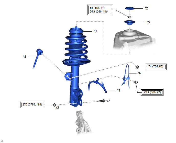
| *1 | FRONT FLEXIBLE HOSE | *2 | FRONT SUSPENSION SUPPORT DUST COVER |
| *3 | FRONT SHOCK ABSORBER WITH COIL SPRING | *4 | FRONT STABILIZER LINK ASSEMBLY |
| *5 | FRONT NO. 2 SUSPENSION SUPPORT | *6 | FRONT SPEED SENSOR |
 | Tightening torque for "Major areas involving basic vehicle performance such as moving/turning/stopping" : N*m (kgf*cm, ft.*lbf) | * | For use with SST |
ILLUSTRATION
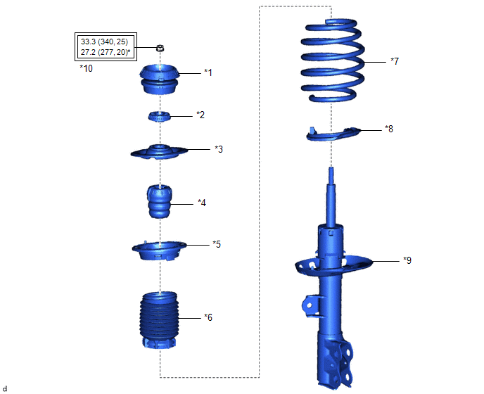
| *1 | FRONT SUSPENSION SUPPORT SUB-ASSEMBLY | *2 | STRUT MOUNTING BEARING |
| *3 | FRONT UPPER COIL SPRING SEAT | *4 | FRONT SPRING BUMPER |
| *5 | FRONT UPPER COIL SPRING INSULATOR | *6 | FRONT NO. 1 SHOCK ABSORBER DUST COVER |
| *7 | FRONT COIL SPRING | *8 | FRONT LOWER COIL SPRING INSULATOR |
| *9 | FRONT SHOCK ABSORBER ASSEMBLY | *10 | FRONT SUPPORT TO FRONT SHOCK ABSORBER NUT |
 | Tightening torque for "Major areas involving basic vehicle performance such as moving/turning/stopping" : N*m (kgf*cm, ft.*lbf) | * | For use with SST |

 Removal
REMOVAL CAUTION / NOTICE / HINT The necessary procedures (adjustment, calibration, initialization, or registration) that must be performed after parts are removed, installed, or replaced during the front shock absorber assembly removal/installation are shown below...
Other information:
Toyota Yaris XP210 (2020-2026) Reapir and Service Manual: Installation
INSTALLATION PROCEDURE 1. INSTALL TURN SIGNAL SWITCH (a) Engage the claw to install the turn signal switch as shown in the illustration. Install in this Direction (b) Install the 2 screws. 2. INSTALL UPPER STEERING COLUMN COVER Click here 3...
Toyota Yaris XP210 (2020-2026) Owner's Manual: Snow Tires
Use snow tires on all four wheels Do not go faster than 75 mph (120 km/h) while driving with snow tires. Inflate snow tires 30 kPa (0.3 kgf/cm2, 4.3 psi) more than recommended on the tire pressure label (driver’s door frame), but never more than the maximum cold-tire pressure shown on the tires...
Categories
- Manuals Home
- Toyota Yaris Owners Manual
- Toyota Yaris Service Manual
- Battery Monitor Module General Electrical Failure (P058A01)
- Immobilizer System
- Brake System Control Module "A" System Voltage System Voltage Low (C137BA2)
- New on site
- Most important about car
Fuel-Filler Lid and Cap
WARNING
When removing the fuel-filler cap, loosen the cap slightly and wait for any hissing to stop, then remove it
Fuel spray is dangerous. Fuel can burn skin and eyes and cause illness if ingested. Fuel spray is released when there is pressure in the fuel tank and the fuel-filler cap is removed too quickly.