Toyota Yaris: Cruise Control / Camera Heater
Components
COMPONENTS
ILLUSTRATION
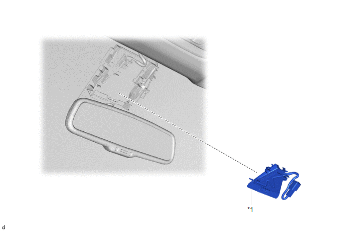
| *1 | FORWARD RECOGNITION WITH HEATER HOOD SUB-ASSEMBLY | - | - |
Removal
REMOVAL
PROCEDURE
1. REMOVE FORWARD RECOGNITION CAMERA
Click here

2. REMOVE FORWARD RECOGNITION WITH HEATER HOOD SUB-ASSEMBLY
NOTICE:
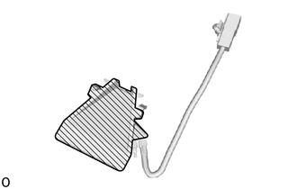
- Do not touch the inner surface of the forward recognition with heater hood sub-assembly.
- Do not apply force to the heating element of the forward recognition with heater hood sub-assembly or an open circuit may result.

 | Inner Surface of Forward Recognition with Heater Hood Sub-assembly |
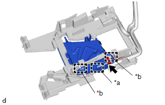
| (a) Disconnect the connector. NOTICE: Do not pull the harness forcibly when disconnecting the connector. |
|
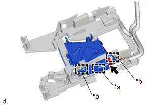
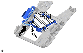
(b) Disengage the clamp and ribs.
(c) Disengage the claws and guides to remove the forward recognition with heater hood sub-assembly as shown in the illustration.
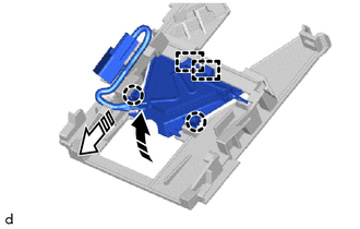
 | Remove in this Direction (1) |
 | Remove in this Direction (2) |
Installation
INSTALLATION
PROCEDURE
1. INSTALL FORWARD RECOGNITION WITH HEATER HOOD SUB-ASSEMBLY
NOTICE:
-
Do not touch the inner surface of the forward recognition with heater hood sub-assembly.

Inner Surface of Forward Recognition with Heater Hood Sub-assembly
- Do not apply force to the heating element of the forward recognition with heater hood sub-assembly or an open circuit may result.
(a) Engage the guides and claws to install the forward recognition with heater hood sub-assembly as shown in the illustration.
 | Heater Area |
 | Install in this Direction (1) |
 | Install in this Direction (2) |
NOTICE:
- Make sure that the claws are engaged as shown in the illustration. Failure to do so may result in the malfunction of systems that use the forward recognition camera.
- Do not apply force to the heating element of the forward recognition with heater hood sub-assembly or an open circuit may result.
| (b) Engage the clamp and ribs. NOTICE:
|
|
(c) Connect the connector.
2. INSTALL FORWARD RECOGNITION CAMERA
Click here


Other information:
Toyota Yaris XP210 (2020-2026) Reapir and Service Manual: Components
COMPONENTS ILLUSTRATION *1 BRAKE PEDAL PAD *2 BRAKE PEDAL RETURN SPRING *3 BRAKE PEDAL SUPPORT ASSEMBLY *4 PUSH ROD PIN *5 STOP LIGHT SWITCH MOUNTING ADJUSTER *6 BRAKE MASTER CYLINDER PUSH ROD CLEVIS *7 CLEVIS LOCK NUT *8 WIRE HARNESS *9 STOP LIGHT SWITCH ASSEMBLY - - Tightening torque for "Major areas involving basic vehicle performance such as moving/turning/stopping" : N*m (kgf*cm, ft...
Toyota Yaris XP210 (2020-2026) Reapir and Service Manual: Inspection
INSPECTION PROCEDURE 1. INSPECT FRONT DRIVE SHAFT ASSEMBLY (a) Check that there is no excessive play in the radial direction of the outboard joint. (b) Check that the inboard joint slides smoothly in the thrust direction. (c) Check that there is no excessive play in the radial direction of the inboard joint...
Categories
- Manuals Home
- Toyota Yaris Owners Manual
- Toyota Yaris Service Manual
- Maintenance
- Fuse Panel Description
- Removal
- New on site
- Most important about car
Turning the Engine Off
Stop the vehicle completely. Manual transaxle: Shift into neutral and set the parking brake.Automatic transaxle: Shift the selector lever to the P position and set the parking brake.
Press the push button start to turn off the engine. The ignition position is off.