Toyota Yaris: Lighting (int) / Back Door Courtesy Switch
Components
COMPONENTS
ILLUSTRATION
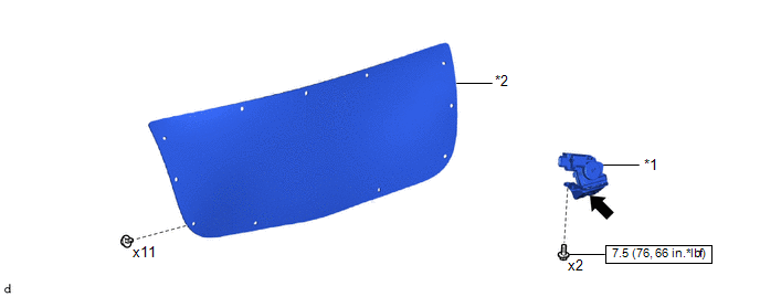
| *1 | BACK DOOR LOCK ASSEMBLY WITH COURTESY LIGHT SWITCH | *2 | BACK DOOR TRIM BOARD |
 | N*m (kgf*cm, ft.*lbf): Specified torque |
 | MP grease |
Removal
REMOVAL
CAUTION / NOTICE / HINT
Click here

Inspection
INSPECTION
PROCEDURE
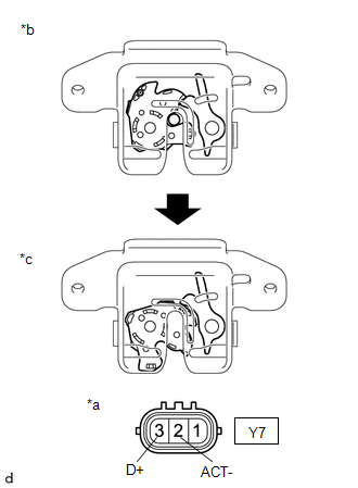
1. INSPECT BACK DOOR LOCK ASSEMBLY WITH COURTESY LIGHT SWITCH
(a) Check the resistance.
| (1) Measure the resistance according to the value(s) in the table below. Standard Resistance:
If the result is not as specified, replace the back door lock assembly with courtesy light switch. |
|
 Ambient Light
ComponentsCOMPONENTS ILLUSTRATION
*A for Driver Side *B for Front Passenger Side *1 MULTIPLEX NETWORK MASTER SWITCH ASSEMBLY WITH FRONT ARMREST BASE UPPER PANEL *2 POWER WINDOW REGULATOR SWITCH ASSEMBLY WITH FRONT ARMREST BASE UPPER PANEL *3 NO...
 Front Door Courtesy Switch
ComponentsCOMPONENTS ILLUSTRATION
*1 FRONT DOOR COURTESY LIGHT SWITCH ASSEMBLY - -
N*m (kgf*cm, ft.*lbf): Specified torque - - RemovalREMOVAL CAUTION / NOTICE / HINT HINT:
Use the same procedure for the RH side and LH side...
Other information:
Toyota Yaris XP210 (2020-2026) Owner's Manual: Wiper Blades
Contamination of either the windshield or the blades with foreign matter can reduce wiper effectiveness. Common sources are insects, tree sap, and hot wax treatments used by some commercial car washes. If the blades are not wiping properly, clean the window and blades with a good cleaner or mild detergent; then rinse thoroughly with clean water...
Toyota Yaris XP210 (2020-2026) Owner's Manual: Active Adaptive Shift (AAS)
Active Adaptive Shift (AAS) automatically controls the transaxle shift points to best suit the road conditions and driver input. This improves driving feel. The transaxle may switch to AAS mode when driving up and down slopes, cornering, driving at high elevations, or depressing the accelerator pedal quickly while the selector lever is in the D position...
Categories
- Manuals Home
- Toyota Yaris Owners Manual
- Toyota Yaris Service Manual
- Key Battery Replacement
- Engine Start Function When Key Battery is Dead
- Engine & Hybrid System
- New on site
- Most important about car
Key Suspend Function
If a key is left in the vehicle, the functions of the key left in the vehicle are temporarily suspended to prevent theft of the vehicle.
To restore the functions, press the unlock button on the functions-suspended key in the vehicle.