
Toyota Yaris: Heating / Air Conditioning / Air Conditioning Filter
Toyota Yaris XP210 (2020-2026) Reapir and Service Manual / Vehicle Interior / Heating / Air Conditioning / Air Conditioning Filter
Components
COMPONENTS
ILLUSTRATION
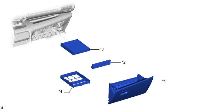
| *1 | GLOVE COMPARTMENT DOOR ASSEMBLY | *2 | AIR FILTER COVER PLATE |
| *3 | CLEAN AIR FILTER | *4 | COOLING UNIT PARTS |
 Installation
INSTALLATION PROCEDURE 1. INSTALL AIR CONDITIONING AMPLIFIER ASSEMBLY (a) Connect the 3 connectors.
(b) Engage the guide to install the air conditioning amplifier assembly...

Other information:
Toyota Yaris XP210 (2020-2026) Reapir and Service Manual: Installation
INSTALLATION PROCEDURE 1. INSTALL FLOOR SHIFT SHIFT LEVER ASSEMBLY (a) Install the floor shift shift lever assembly to the vehicle body with the 4 bolts. Torque: 12 N·m {122 kgf·cm, 9 ft·lbf} (b) Engage the 4 clamps to connect the wire harness to the floor shift shift lever assembly...
Toyota Yaris XP210 (2020-2026) Reapir and Service Manual: Lost Communication with Cruise Control Front Distance Range Sensor Single Sensor or Center Missing Message (U023587)
DESCRIPTION The forward recognition camera and millimeter wave radar sensor assembly communicate via CAN communication. If there is an error in the communication with the millimeter wave radar sensor assembly, the forward recognition camera stores DTC U023587...
Categories
- Manuals Home
- Toyota Yaris Owners Manual
- Toyota Yaris Service Manual
- Opening and Closing the Liftgate/Trunk Lid
- How to use USB mode
- Auto Lock/Unlock Function
- New on site
- Most important about car
Break-In Period
No special break-in is necessary, but a few precautions in the first 600 miles (1,000 km) may add to the performance, economy, and life of the vehicle.
Do not race the engine. Do not maintain one constant speed, either slow or fast, for a long period of time. Do not drive constantly at full-throttle or high engine rpm for extended periods of time. Avoid unnecessary hard stops. Avoid full-throttle starts.
Copyright © 2026 www.toyaris4.com