Toyota Yaris: Gf1a (transfer / 4wd / Awd) / 4wd Control Switch
Components
COMPONENTS
ILLUSTRATION
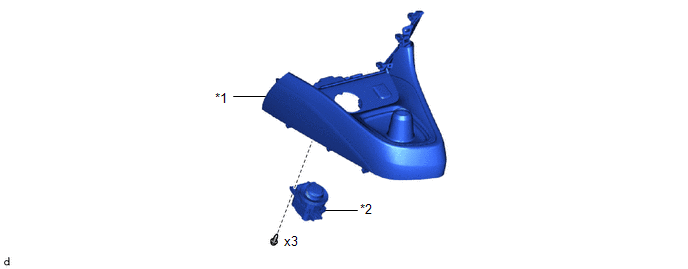
| *1 | CONSOLE BOX ASSEMBLY | *2 | 4WD CONTROL SWITCH (NO. 2 COMBINATION SWITCH ASSEMBLY) |
Removal
REMOVAL
PROCEDURE
1. REMOVE CONSOLE BOX ASSEMBLY
Click here

2. REMOVE 4WD CONTROL SWITCH (NO. 2 COMBINATION SWITCH ASSEMBLY)
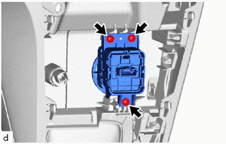
| (a) Remove the 3 screws and 4WD control switch (No. 2 combination switch assembly). |
|
Inspection
INSPECTION
PROCEDURE
1. INSPECT 4WD CONTROL SWITCH (NO. 2 COMBINATION SWITCH ASSEMBLY)
(a) Inspect the resistance:
| (1) Measure the resistance according to the value(s) in the table below. Standard Resistance:
|
|
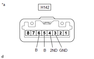
(2) If the result is not as specified, replace the 4WD control switch (No. 2 combination switch assembly).
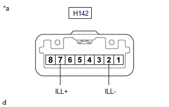
| (b) Inspect the illumination: (1) Apply battery voltage to the integration control and panel assembly (multi-terrain select switch) and check that the switch illuminates. OK:
(2) If the result is not as specified, replace the 4WD control switch (No. 2 combination switch assembly). |
|
Installation
INSTALLATION
PROCEDURE
1. INSTALL 4WD CONTROL SWITCH (NO. 2 COMBINATION SWITCH ASSEMBLY)
(a) Install the 4WD Control switch (No. 2 combination switch assembly) with the 3 screws.
2. INSTALL CONSOLE BOX ASSEMBLY
Click here

 4wd Control Ecu
ComponentsCOMPONENTS ILLUSTRATION
*1 DECK TRIM SIDE PANEL ASSEMBLY RH *2 4WD ECU ASSEMBLY
N*m (kgf*cm, ft.*lbf): Specified torque - - RemovalREMOVAL CAUTION / NOTICE / HINT The necessary procedures (adjustment, calibration, initialization, or registration) that must be performed after parts are removed and installed, or replaced during the 4WD ECU removal/installation are shown below...

Other information:
Toyota Yaris XP210 (2020-2026) Reapir and Service Manual: Terminals Of Ecu
TERMINALS OF ECU CHECK CERTIFICATION ECU (SMART KEY ECU ASSEMBLY) (a) Disconnect the H45 and H46 certification ECU (smart key ECU assembly) connectors. (b) Measure the resistance and voltage according to the value(s) in the table below. HINT: Measure the values on the wire harness side with the connector disconnected...
Toyota Yaris XP210 (2020-2026) Reapir and Service Manual: Check For Intermittent Problems
CHECK FOR INTERMITTENT PROBLEMS NOTICE: If the vehicle or vehicle controls are operated (for example, during initial inspection when the vehicle is brought in for repair) before vehicle control history (RoB) has been read out and saved, the vehicle control history (RoB) information could be lost...
Categories
- Manuals Home
- Toyota Yaris Owners Manual
- Toyota Yaris Service Manual
- Engine & Hybrid System
- G16e-gts (engine Mechanical)
- Fuel Gauge
- New on site
- Most important about car
Front Seat Belt Pretensioners
The front seat belt pretensioners are designed to deploy in moderate or severe frontal, near frontal collisions.
In addition, the pretensioners operate when a side collision or a rollover accident is detected. The pretensioners operate differently depending on what types of air bags are equipped. For more details about the seat belt pretensioner operation, refer to the SRS Air Bag Deployment Criteria.