Toyota Yaris: Air Conditioning System / Operation not Accepted Even If Air Conditioning Switch is Operated
DESCRIPTION
If the air conditioning system cannot be operated using the air conditioning control assembly, the following factors may be the cause.
| Symptom | Factor |
|---|---|
| Air conditioning system cannot be operated using air conditioning control assembly
|
|
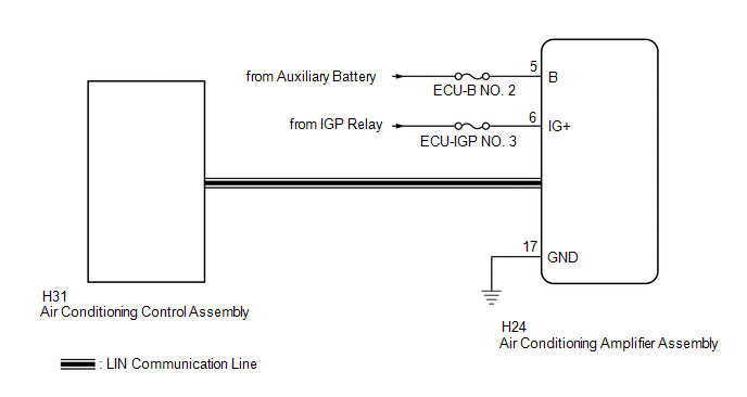
WIRING DIAGRAM
CAUTION / NOTICE / HINT
NOTICE:
Inspect the fuses for circuits related to this system before performing the following procedure.
PROCEDURE
| 1. | CHECK FOR DTC |
(a) Clear the DTCs.
Body Electrical > Air Conditioner > Clear DTCs(b) Check for DTCs.
Body Electrical > Air Conditioner > Trouble Codes| Result | Proceed to |
|---|---|
| B14B287 is not output | A |
| B14B287 is output | B |
| B |
 | GO TO DTC B14B287 |
|

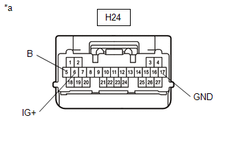
| 2. | CHECK HARNESS AND CONNECTOR (AIR CONDITIONING AMPLIFIER ASSEMBLY - POWER SOURCE AND BODY GROUND) |
(a) Disconnect the air conditioning amplifier assembly connector.
| (b) Measure the voltage and resistance according to the value(s) in the table below. Standard Voltage:
Standard Resistance:
|
|
| OK |
 | REPLACE AIR CONDITIONING AMPLIFIER ASSEMBLY |
| NG |
 | REPAIR OR REPLACE HARNESS OR CONNECTOR |
 Cooling is Poor
DESCRIPTION If the cooling effect of the air conditioning system is weak, the following factors may be the cause. Symptom Factor
Cooling effectiveness is poor
Cooling response is slow
ECO drive mode function (air flow volume is restricted due to ECO drive mode being selected)
Compressor with pulley assembly malfunction
Refrigerant volume (high)
Refrigerant volume (low)
Clogged cooler condenser assembly fins
Cooling fan system malfunction
Mechanical locking of damper and damper link
Automatic light control sensor malfunction
High inlet air temperature
PROCEDURE 1...
 Front Window Fogging
DESCRIPTION If the windshield frequently fogs up even though the air conditioning system is operating, the following factors may be the cause. Symptom Factor Windshield frequently fogs up
Compressor malfunction
Refrigerant volume (low)
Cooler expansion valve (opened excessively)
No...
Other information:
Toyota Yaris XP210 (2020-2026) Reapir and Service Manual: Tongue Plate Stopper
ComponentsCOMPONENTS ILLUSTRATION *1 TONGUE PLATE STOPPER - - ● Non-reusable part - - ReplacementREPLACEMENT PROCEDURE 1. REMOVE TONGUE PLATE STOPPER (a) Slide the tongue plate above the installation position of the tongue plate stopper, and temporarily hold it with adhesive tape...
Toyota Yaris XP210 (2020-2026) Reapir and Service Manual: Problem Symptoms Table
PROBLEM SYMPTOMS TABLE HINT: Use the table below to help determine the cause of problem symptoms. If multiple suspected areas are listed, the potential causes of the symptoms are listed in order of probability in the "Suspected Area" column of the table...
Categories
- Manuals Home
- Toyota Yaris Owners Manual
- Toyota Yaris Service Manual
- Immobilizer System
- Opening and Closing the Liftgate/Trunk Lid
- Fuel Gauge
- New on site
- Most important about car
Fuel Gauge
The fuel gauge shows approximately how much fuel is remaining in the tank when the ignition is switched ON. We recommend keeping the tank over 1/4 full.
