Toyota Yaris: Smart Key System (for Start Function) / Operation Check
OPERATION CHECK
CHECK CUSTOMIZE PARAMETERS
(a) The operation check below is based on the non-customized initial condition of the vehicle.
Click here

CHECK PUSH-BUTTON START FUNCTION
(a) Check the push-button start function:
(1) Get into the vehicle while carrying the electrical key transmitter sub-assembly with the ignition switch off, check that the key indicator display is displayed when the clutch pedal is depressed. Check that the engine starts when the engine switch is pressed after the key indicator display is displayed on the multi-information display.
(2) While carrying the electrical key transmitter sub-assembly, check that the power source mode changes in the following order when the engine switch is pressed with the clutch pedal released: off → ACC → ON → off.
(3) Check that the steering lock operates when a door is opened.
(4) Check the push-button start function operation range for the front side. Place the electrical key transmitter sub-assembly at either inspection point so that it is facing the direction shown in the illustration, and then check that the engine can be started.
NOTICE:
Even if the electrical key transmitter sub-assembly is in a vehicle interior detection area, it may not be properly detected if it is on the instrument panel, in the glove box or on the floor.
HINT:
-
Communication may not be possible if the electrical key transmitter sub-assembly is within 0.2 m (0.656 ft.) of the No. 1 indoor electrical key antenna assembly (front floor).
Click here

- Perform this inspection for both inspection points.
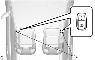
| *a | Inspection Point |
(5) Check the push-button start function operation range for the rear side. Place the electrical key transmitter sub-assembly at either inspection point so that it is facing the direction shown in the illustration, and then check that the engine can be started.
NOTICE:
Even if the electrical key transmitter sub-assembly is in a vehicle interior detection area, it may not be properly detected if it is on the instrument panel, in the glove box or on the floor.
HINT:
-
Communication may not be possible if the electrical key transmitter sub-assembly is within 0.2 m (0.656 ft.) of the center of the No. 2 indoor electrical key antenna assembly (rear floor).
Click here

- Perform this inspection for both inspection points.
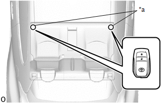
| *a | Inspection Point |
CHECK POWER SOURCE MODE CHANGING FUNCTION
(a) Check the engine switch.
(1) Check that the power source mode changes according to the chart below.
| Clutch Pedal | Power Source Mode when Engine Switch Pressed |
|---|---|
| Released | Off → ACC → ON → off |
| Released | Engine running → off |
| Depressed | Off → engine starts |
| Depressed | ACC → engine starts |
| Depressed | ON → engine starts |
| Depressed | Engine running → off |
CHECK TRANSMITTER BATTERY SAVING MODE FUNCTION
(a) Check the transmitter battery saving mode function:
(1) Press the unlock switch of the electrical key transmitter sub-assembly twice while pressing the lock switch and check that the electrical key transmitter sub-assembly LED blinks 4 times and enters transmitter battery saving mode.
(2) Check that the smart key system does not operate while in transmitter battery saving mode.
HINT:
To cancel transmitter battery saving mode, press a switch of the electrical key transmitter sub-assembly.
CHECK ENTRY CANCEL FUNCTION
(a) Disable the smart key system and check that all functions of the smart key system no longer operate.
Click here

HINT:
When the smart key system is disabled, it is possible to lock and unlock the doors with the wireless function, and the engine can be started by holding the electrical key transmitter sub-assembly near the engine switch.
CHECK KEY DIAGNOSTIC MODE
Click here

 Check For Intermittent Problems
CHECK FOR INTERMITTENT PROBLEMS NOTICE:
Operation history is stored in the RAM or EEPROM of the certification ECU (smart key ECU assembly). As the cause of a malfunction stored in the RAM will be cleared when the cable is disconnected from the negative (-) battery terminal, do not disconnect the cable from the negative (-) battery terminal before checking and recording are complete...
 Registration
REGISTRATION PROCEDURE 1. REPAIR INSTRUCTION CAUTION: As weak radio waves are emitted from the electrical key transmitter sub-assembly, if a pacemaker is being used, be sure to read the pacemaker instruction manual and the following...
Other information:
Toyota Yaris XP210 (2020-2026) Reapir and Service Manual: Diagnosis System
DIAGNOSIS SYSTEM DESCRIPTION (a) Power window control system data and Diagnostic Trouble Codes (DTCs) can be read through the vehicle Data Link Connector 3 (DLC3). When the system seems to be malfunctioning, use the GTS to check for malfunctions and perform repairs...
Toyota Yaris XP210 (2020-2026) Owner's Manual: Manual Transaxle Shift Pattern
The shift pattern of the transaxle is conventional, as shown. Depress the clutch pedal all the way down while shifting; then release it slowly. Your vehicle is equipped with a device to prevent shifting to R (reverse) by mistake. Push the shift lever downward and shift to R...
Categories
- Manuals Home
- Toyota Yaris Owners Manual
- Toyota Yaris Service Manual
- Fuse Panel Description
- Key Battery Replacement
- Opening and Closing the Liftgate/Trunk Lid
- New on site
- Most important about car
Fuel Gauge
The fuel gauge shows approximately how much fuel is remaining in the tank when the ignition is switched ON. We recommend keeping the tank over 1/4 full.
