Toyota Yaris: Air Conditioning System / Lost Communication with Front Panel LIN Missing Message (B14B287)
DESCRIPTION
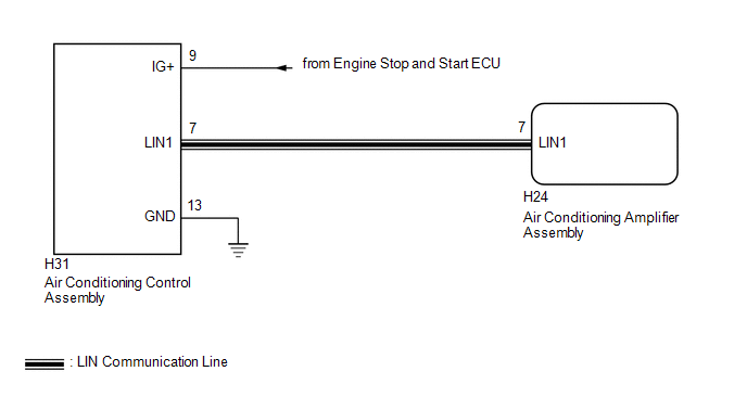
The air conditioning control assembly communicates with the air conditioning amplifier assembly via LIN communication.
If a malfunction occurs in the LIN communication system, the air conditioning amplifier assembly will not operate, even if the air conditioning control assembly is operated.
| DTC No. | Detection Item | DTC Detection Condition | Trouble Area | Memory |
|---|---|---|---|---|
| B14B287 | Lost Communication with Front Panel LIN Missing Message | Diagnosis Condition:
Malfunction Status:
Detection Time:
|
| Memorized |
| Vehicle Condition | |||
|---|---|---|---|
| Pattern 1 | Pattern 2 | ||
| Diagnosis Condition | Ignition switch ON | ○ | ○ |
| Malfunction | Error communication with air conditioning control assembly | ○ | - |
| Lost communication with air conditioning control assembly | - | ○ | |
| Detection Time | Continuously for 10 seconds or more | Continuously for 10 seconds or more | |
| Trip Count | 1 trip | 1 trip | |
HINT:
If the conditions of either of these patterns are detected, a DTC will be stored.
WIRING DIAGRAM
CAUTION / NOTICE / HINT
NOTICE:
Inspect the fuses for circuits related to this system before performing the following procedure.
PROCEDURE
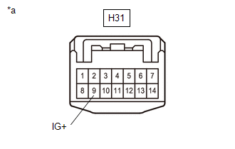
| 1. | CHECK HARNESS AND CONNECTOR (AIR CONDITIONING CONTROL ASSEMBLY - IG POWER SOURCE) |
(a) Disconnect the air conditioning control assembly connector.
| (b) Measure the voltage according to the value(s) in the table below. Standard Voltage:
|
|
| NG |
 | REPAIR OR REPLACE HARNESS OR CONNECTOR |
|

| 2. | CHECK HARNESS AND CONNECTOR (AIR CONDITIONING CONTROL ASSEMBLY - BODY GROUND) |
(a) Measure the resistance according to the value(s) in the table below.
Standard Resistance:
| Tester Connection | Condition | Specified Condition |
|---|---|---|
| H31-13 (GND) - Body ground | Always | Below 1 Ω |
| NG |
 | REPAIR OR REPLACE HARNESS OR CONNECTOR |
|

| 3. | CHECK HARNESS AND CONNECTOR (AIR CONDITIONING CONTROL ASSEMBLY - AIR CONDITIONING AMPLIFIER ASSEMBLY) |
(a) Disconnect the H24 air conditioning amplifier assembly connector.
(b) Measure the resistance according to the value(s) in the table below.
Standard Resistance:
| Tester Connection | Condition | Specified Condition |
|---|---|---|
| H31-7 (LIN1) - H24-7 (LIN1) | Always | Below 1 Ω |
| H31-7 (LIN1) or H24-7 (LIN1) - Other terminals and body ground | Always | 10 kΩ or higher |
| NG |
 | REPAIR OR REPLACE HARNESS OR CONNECTOR |
|

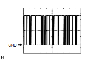
| 4. | INSPECT AIR CONDITIONING AMPLIFIER ASSEMBLY |
(a) Connect the H24 air conditioning amplifier assembly connector.
| (b) Using an oscilloscope, check the waveform.
OK: Waveform is similar to that shown in the illustration. |
|
| NG |
 | REPLACE AIR CONDITIONING AMPLIFIER ASSEMBLY |
|

| 5. | INSPECT AIR CONDITIONING CONTROL ASSEMBLY |
| (a) Connect the air conditioning control assembly connector. |
|
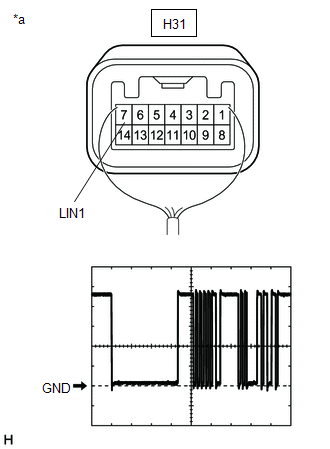
(b) Using an oscilloscope, check the waveform.
| Item | Content |
|---|---|
| Terminal No. | H31-7 (LIN1) - Body ground |
| Tool Setting | 2 V/DIV., 20 ms./DIV. |
| Condition | Ignition switch ON |
OK:
Waveform is similar to that shown in the illustration.
| OK |
 | REPLACE AIR CONDITIONING AMPLIFIER ASSEMBLY |
| NG |
 | REPLACE AIR CONDITIONING CONTROL ASSEMBLY |
 Front Right Air Mix Damper Control Servo Motor Actuator Stuck Off (B145B7F)
DESCRIPTION The No. 1 air conditioning radiator damper servo sub-assembly sends pulse signals to inform the air conditioning amplifier assembly of the damper position...
 Ambient Temperature Sensor Circuit Short to Ground (P007011)
DESCRIPTION The thermistor assembly is installed in front of the cooler condenser assembly to detect the ambient temperature, which is used to control the air conditioning system...
Other information:
Toyota Yaris XP210 (2020-2026) Reapir and Service Manual: Components
C..
Toyota Yaris XP210 (2020-2026) Reapir and Service Manual: Heavy Steering Feel (EPS Warning Light (Yellow))
PROCEDURE 1. READ VALUE USING GTS (a) Read the Data List according to the display on the GTS. Chassis > EMPS > Data List Tester Display Measurement Item Range Normal Condition Diagnostic Note Battery Voltage Drop History Number of times vehicle auxiliary battery voltage dropped Min...
Categories
- Manuals Home
- Toyota Yaris Owners Manual
- Toyota Yaris Service Manual
- Brake System Control Module "A" System Voltage System Voltage Low (C137BA2)
- Adjustment
- Auto Lock/Unlock Function
- New on site
- Most important about car
Key Suspend Function
If a key is left in the vehicle, the functions of the key left in the vehicle are temporarily suspended to prevent theft of the vehicle.
To restore the functions, press the unlock button on the functions-suspended key in the vehicle.